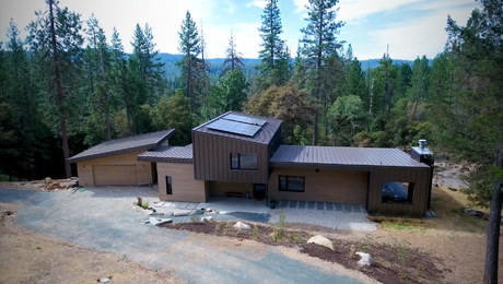
Hip angles on square cut tail hip roof.
Hello all, I have been gone for a while and I missed all the great info and wisdom on this site. I have a question for the carpenters out there. I just did a remodel on an existing garage and the tails were cut square. The roof pitch was 4/12 and it was a hip that blended with an existing wall on one side. I went to do the facia board today ( heart redwood 1×8, beautifull! ) when I went to cut the ends of the hips where the facia was going to meet in an outside corner, I realized that I didn’t know a “right” way to find the angles to cut the hips at. It is the same problem I run into cutting in frieze blocks at valleys. I do this by the ol’ string and measure top and bottom method but I know there has to be a ‘correct’ way to get this compound angle. I have a sneeking suspicion that it is in my Reichers Full Legnth Roof Framer book somewhere but I do not know what angle it is. Do you? Any help out there for an anal ‘do it right’ carpenter? Thanks for the help y’all.


Replies
Try this thread at JLC http://forums.jlconline.com/forums/showthread.php?t=28059
Joe Bartok explains this stuff so I can almost understand it :-)
robzan: I think this is what you are after, a link to the infamous Square Tail Fascia Calculator.
Just for the record, the balance of that JLC Forum thread discusses a different situation: Square Fascia on a dormer intercepting the plane of the Main roof. This calculator is for Square Tail Fascia at the foot of a Hip-Valley Rafter. Making a mockup or a test cut is definitely a good idea. If you browse the calculator links you'll see that I made Models by developing the angles on bristol board.
For your roof, 4/12 pitch meets 4/12 pitch at a 90° angle between eaves:
Fascia Miter Angle = 17.54840°
Angle on the Fascia = 72.45160° (Complementary to the Miter Angle)
Fascia Bevel Angle = 42.13041°
Hip Rafter Miter Angle = 11.97673°
Hip Rafter Bevel Angle = 42.13041°
The planes of square cut fascia set perpendicular to the plane of the roof are the same planes as on purlins, and the miter and bevel angles on the Hip rafter are the same as used for bird-block, or to cut housings for purlins. For irregular roofs the miter and bevel angles on the fascia are different from those on purlins. Whereas purlins end in a blind pocket the planes of the square fascia continue until they intercept one another.
Good luck, I hope this helps.
Edited 9/30/2005 11:01 am ET by JoeBartok
Edited 9/30/2005 1:21 pm ET by JoeBartok
Edited 9/30/2005 1:28 pm ET by JoeBartok
Thank you for your reply and the link to the calculator Joe. I like your models, that took some time and looks cool too. Thank you for sharing your knowledge with me. Sincerely, Robert Zanfardino
Joe I just saw this one > The square cut raftertail at the hip is called the witch cut by european carpenters. Because only a witch can do it. It is easy to draw and fun to watch people try and do . It gets even better and more fun when you have unequal pitch. Hence the witch cut, or" hex schnit"
robzan, keep in touch and let me know if you have any difficulties. And post some pics!
olle, thanks for the historical background. Actually I was feeling a bit "hexed" on my first effort at this cut. I realized the line on the tail of the Hip would skew for irregular pitches as seen in the models. But somehow I managed to lose my chain of thought and forgot that the planes of the reciprocal pitches (the fascia) actually crossed one another at the Hip tail. So I worked out a whole bunch of formulas that were O.K. for regular pitches but there was no way they would have worked for irregulars. As you can imagine I was a bit bummed out when I sat down to make the first model and ... oops! Back to the old drawing board.Joe Bartok
olle, here's something to think about.
The default values for the calculator assume the fascia is square to the common rafter tails. But isn't it just as easy to solve the cutting angles if we assume the fascia is rotated to any position? It can be plumb, it can be level (i.e. following a soffit, in which case it isn't really fascia), or any angle in between these extremes.
And why restrict the argument to fascia? We can imagine a piece running in the direction of a purlin on the plane of the roof with the other face tilted at any angle.
Joe Bartok
Edited 10/5/2005 4:04 pm ET by JoeBartok
Joe I know what you mean and I have tried to think that way but my background is in drawing, so I get lost in the math . With unequal pitch the intersection line of the two diffrent pitches will as you say come out of the hip or valley on a skew and is hard to visualize. I have a dvd of a German master drawing this exact thing and will send it to you if you want . The approache is interesting and fun to do I have used it several times
Don't feel bad. I didn't get that skew by development either. Nor did I use trigonometry the first time around. I had to use vector products. But now that you've raised the question I'm going to think about how this joint could be developed.
Just some ideas on where to begin, and maybe these sketches will help. The Hip rafter creates its own pitch angle and Plan angles. The reciprocal pitches for the fascia create their own "Hip" and Plan angles. These "Fascia Plan angles" are always the opposite of the plan angles created by the true Hip rafter.
The angles as the fascia intercepts the side (plumb) face of the Hip rafter are the R2 angles, and R3 on the upper shoulder (or the complements of these angles). We can treat each side of the Hip rafter as an independent entity and draw the development as we would any compound angle.
Another idea is: we can treat the sum of the R3 complements on the upper shoulder of the Hip rafter as a "Deck angle". The "Pitch angles" are 90 - C2. The development proceeds as for any Hip roof but there's a slight catch. Watch out for the orientation or tilt of the planes representing the pitches. Viewed in section they both tilt the same way rather than toward one another and I got crossed up on this on my first shot at a trigonometric solution.Joe Bartok
olle, here's what I had in mind in my last post. The attached files and images aren't the best, just whatever I had handy. And I'm certain there's a quicker and more efficient way to develop the angles.
The angles on the Hip Rafter, at Square Tail Fascia intercepts Hip Rafter, are the same as for a Purlin. We can develop the Tetrahedron of Purlin meets Hip Rafter Angles. In this drawing the Miter Angle on side face of Hip Rafter is angle R2, Saw Bevel Angle on face of Purlin Perpendicular to Roof Plane is angle C1. If we're cutting with a power saw we are home free. We only need develop R2 and C1 for the Main and Adjacent sides. If we are cutting by hand we need miter lines on both faces.
Given R2 and C1 we can draw a Development of Angle 90 - R3 on the Stick. Aided by the power and speed of modern computers I made a really dumb mistake in this series of graphics. The angle labelled C2 should read C1. I'll try to get this fixed and re-posted by tomorrow morning.
The planes of the Square Tail Fascia cross one another so we can't always use the angles we would for a Purlin. But we already have 90 - P2 developed on the first tetrahedron. Another tetrahedron may be developed using the reciprocal pitches to determine the angle on the wide face of the fascia. If we're cutting by hand, we're all set. Or, beginning with these two angles as miter lines we can do another "on the stick" development and determine the saw blade angle. 90 - P2 will actually be on the narrow plane of the fascia but we can draw our development on a larger scale since the angles are independent dimensions.
Do you think this process makes sense? I'll try to get that "hexed" C2 angle changed to C1 ASAP, and I'll be reviewing the "logic" of this tonight to ensure there aren't any other errors.
Joe Bartok
Edited 10/7/2005 11:07 am ET by JoeBartok
Edited 10/7/2005 1:04 pm ET by JoeBartok
Edited 10/7/2005 1:05 pm ET by JoeBartok
Edited 10/7/2005 1:06 pm ET by JoeBartok
olle:
The names for the angles in the Development of Angle 90 - R3 on the Stick images are fixed (I hope!).
I tried this development and as near as I can measure with a protractor it works O.K. For the sake of speed I "cheated" a bit by generating the angles on my calculator and doing the layout with a protractor and ruler rather than compass and straightedge. It's well and good to show this can be done in terms of "pure" geometry and the knowledge is a good resource to fall back on if all else fails. But developments can be time consuming and tedious!
I'll try the angles on the fascia tonight and see how they work out.
Enjoy!Joe Bartok