Solutions to stiffen freestanding roof
A general question regarding structural stiffness…
I’m finishing up a freestanding patio roof with the following specs:
concrete footings
Simpson post bases placed in wet concrete
6×6 posts
5x15x32′ beam in back – max span – 26 ft.
4x10x32′ beam in front – max span – 6 ft. (4×4 intermediate posts between 6x6s)
4×6 cross beams hurricane strapped to tops of 32′ beams in line with font and back 6×6 posts
4×4 knee bracing along both axes (5 1/2′ long) bolted with 3/4″x10″ galv. lag screws
and the bastard wobbles like a mother. Lateral (side to side) movement is nil but from front to back is very noticeable. I thought the knee bracing would stiffen things up. This plan was engineered by a firm in town but I’m not comfortable leaving the roof in this state.
My thought is to run two more posts at an angle from top of front posts down to a concrete footing poured 2 ft. into the ground and connected to a post base. That would prevent any front to back motion.
My question is, what solutions have you come up with to stiffen a freestanding structure where all the weight is sitting on four legs?
Thanks, and hello. I’m new to this forum but not to Fine Homebuilding. I enjoy reading the magazine and wanted to talk and bounce ideas around with other 20 percenters.
John


Replies
Any chance we could get some pictures?
You do not examine legislation in the light of the benefits it will convey if properly administered, but in the light of the wrongs it would do and the harms it would cause if improperly administered [Lyndon Johnson]
I'd have poured metal columns deep into the concrete footings. Vertically cantilevered if you will. FHB did an article sometime ago about a freestanding carport and that is what the author did. I can see it would be solid as a rock.
But at this point, I think your only choice is to add some diagonal bracing of some kind. I think you are on the right track. Some pictures would help.
MERC
DJ ... another factor in that carport article was a frame of steel beams embedded in the foundation, so the four corner posts were tied togethert below grade.
Whenever you are asked if you can do a job, tell'em "Certainly, I can!" Then get busy and find out how to do it. T. Roosevelt
I dunno....don't remember that detail. Have to look it up sometime. I do remember steel beams being used at the top of the posts, but not below grade. I recall steel columns being set maybe 4' into concrete footings.
MERC.
The 26' span sounds long. Knee-bracing into that will not provide much stiffness. The knee braces sound short... 5-1/2' foot diagonal at 45 degrees braces down/out less than 4 feet.
I'll take my wife's digital camera and get a couple of pics posted in the next day or so.
The 26 ft. span is because the owner didn't want any posts in the deck itself so the two back posts are on either side of the 22 ft. deck.
The knee bracing is down 4 ft. off the post top - these are 8-9 ft. tall posts so larger knee bracing means much head banging (the bad kind) entering and exiting off the sides of the deck.
Hindsight being what it is, I should've gone with deeper footings, tarred the bottom of the 6x6s and dropped them down into the concrete a couple of feet - or gone with the similar metal post idea suggested above.
Thanks for the replies, I'll get pics up soon.
John
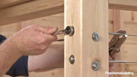
Could you describe the actual post base you used under the 6x6? CB style would have been the best, IMHO.
Unfortunately, there are no bases that come up all four sides of the post, unless you get some specially fabricated, so I think that the sway is influenced by the positioning of the base. Without pics, I'm guessing that the post wobbles opposite the steel coming up the side of the post.
Additionally, you said strapping over? the cross beams. What type of column cap are you using to hold the major beams to the top of the 6x6 posts.? If you are not using a rugged connection, such as the EC or ECC styles you have missed an important degree of stiffness. Those massive pieces of formed steel are not just useful as uplift connectors but also for torsion control which will tranlate downward to offset the "wobble". How much on your application I don't know. Instead of the hurricane straps I would have also considered a more massive connection for the cross beams to the mains.
Any chance you can tie diagonally from the back corners to the front over top of everything now in place? That way, you'd be tying the "wobbly" side into the "stiffer" side.
Soory it took so long to get some pics uploaded - I do appreciate the thoughts you guys are putting into this problem.
Post bases are Simpson PB66 - the kind with the metal curly qs on the shaft that you place in the wet cement.
Conectors for the 6x6 post to beams are Simpson BC6 and BC64 (or BC46).
The post anchors keep the bottom of the post from moving but don't have any strength to keep the post from leaning. The top brackets don't have a great deal of strength either as far as lateral movement goes. Because everything is built, you could add a big X brace from corner to corner under the rafters. Something as simple as a 2x4 with two spikes/screws in each rafter will take the sway out of it. Just run from the upper right to the lower left and the upper left to the lower right. Make sure it's plumb before you run the braces.
Beat it to fit / Paint it to match
One problem I see is that some of the bracing attaches to rafters, which will deflect under the pressure applied to them. The braces in the other direction connect to the beams, which should have more resistance to deflection. All of the braces connect to the posts near their midpoints, which is where they are most subject to deflection. It looks like one bolt connects each brace at the posts. In general there's probably enough lumber to keep it standing, but it will wobble. The solutions would be to make longer braces (connect to the posts near the ground), break the span on the long beam, add braces to the intermediate posts along the other beam, and double or triple the rafters at the braces. Diagonal bracing nailed across the bottoms of the rafters, from corner to corner, might add something. Also, the ends of the glulams are exposed to rain and should be flashed or possibly painted.
I think you should tell the owners that more bracing and posts are needed.
From your pics and description you didn't use any of the serious connectors to assist in gaining stiffness from the top down. Balancing the posts on those skimpy bases didn't help, either. If you'll notice, Simpson doesn't really recommend their post bases for non-top supported structures, such as fences, and this IS a non-top supported structure, even if it isn't a fence.
You have 3 6x6's adjacent to the house. I would suggest a steel pipe or rod, straight back from each post to the house (just under the soffit) with a flange welded to each end so that you can screw the pipes to both the house and the posts. These will be out of the way and almost invisible, as opposed to those monster braces you have and are proposing. Now you will have a top supported structure and you could still keep the knee braces and possibly make them a bit shorter to gain some head room off the end of the deck. Less work, less cost and less useless mass hanging off your work.
To further disguise the pipes or rods you could add a decorative lighting fixture under and attached to each. Use your imagination for a little mood lighting.
I have another idea if that doesn't strike you but it's more work, more cost and more mass.<G>
I didn't know that Simpson said that about their connectors, it makes sense, I just didn't think about it.
I will definitely learn from this experience and bury my posts (in concrete) on future projects.
I like the idea of metal posts tied into the house, much less obtrusive than 6x6 angle braces off the front of the roof into the ground
I was under the impression that once the engineer had looked over the plans and come up with an engineered solution, the structure was good to go. I gave him the plan and he came up with the beam sizes, metal connectors, knee bracing layouts, lag screw size/placement, etc. My thought is now that the engineer should have known not to use Simpson connectors in this case. I'm not trying to transfer blame to him for my inexperience, it was just a learning experience - don't rely on engineers to make sure the structure is built correctly.
Thanks for your constructive criticisms - I'll have this thing solid before I walk away.
John
"it was just a learning experience"
and a leaning experience :)
At this point I would recommend supporting each corner in turn with a temporary jack post and replacing the 4x4 posts with heavy wall steel (primed and painted). Set the steel posts at least 30" into the ground and pour cement to fill the holes. 36" deep would be even better. Those 4x4 posts are just too flexible (wimpy) to make that large structure solid, even IF they were properly set into the ground. Around here they would make me bell the bottom of the holes which I do with a small curved trenching shovel. I would have sized those posts up to 6x6 and set them into cement if I had done it from scratch. That would have also required some changes in the beaming to make it look proper. The steel posts will do the trick now though (be sure to get at least 5/16" thick walls on the posts ... for stiffness). I usually drill a couple of holes through the posts so that they will key into the cement ... for uplift resistance.
I think your wobble comes form the way you braced it front-to-back. (Parallel with the rafters)
You braced from the post up to the rafters. But you have a hinge point where the beam sits on the top of the post.
Adding another brace from the rafter down to the bottom of the beam/top of the post might help.
And I agree with the others who said the posts should have been imbedded in the ground.Why you have to click on "Start" to stop Windows?
Mac,
Diagonal braces under the joist will not help that much, because the wobble is from the posts, as the roof is already sheathed.
The easiest and cheapest soulution I see is to add a cross beam from front to back between the two headers on each end. Then add two more posts just to the hillside/back of the two steps, You might want to use 4x4 steel and cover them with wood for strenght and apperence. Then add a X brace to the back side of the new posts and a diagonal one to the front.
Maybe the rough sketch below can explain better than my keybord. It , the keybord can't, even speel it's own name.
SamT
View Image