
Organizing a Panel Box
To create an orderly panel, plan where everything will go and then methodically execute that plan.
A neat, well-organized service panel or subpanel is easier and safer to work in; it will also be an easier panel in which to add circuits later on.

Label circuits
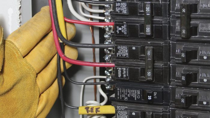
Labeling cables at outlets is important so that when it comes time to attach wires to devices, you’ll always know which switch controls which circuit. Labeling is equally important—perhaps more important—to identify the many cables converging on a panel box. Before you run each cable to the panel, use a permanent marker to write—right on the end of the Romex sheathing—which circuit the cable feeds: “Kitch A,” “Bath B,” “2d Flr Lights,” and so on.
Remove knockouts, insert connectors
Typically, most cables will approach and enter the panel from one direction—from above, if the panel is in the basement. Remove knockouts for the cables, starting with the largest cables, which take up more room and, being stiffer, are more difficult to muscle into place. Insert a cable connector (clamp) into each knockout you remove. Large feeder cables (#4AWG or larger) require insulated fittings (bushings) to protect wire insulation from sharp conduit edges. Most Romex cable, however, doesn’t require bushings—just appropriately sized cable connectors. Larger circuit cable (#10AWG and #8AWG) fits one per connector, but most household circuit cable (#12AWG or #14AWG) can fit two to a connector—but never more than two. (Cable connectors’ capacity is marked on the box or the instruction sheet.)
| PRO TIP: Wiring a panel is complicated, so many electricians divide the task into steps—cutting wires to length, stripping wire ends, bending wires toward a bus, tightening bus screws—and perform each step on all wires before going on to the next step. This greatly speeds a task because each step typically requires only one tool. |
Strip sheathing, identify hots
Once you have pulled cables into the box and tightened cable connectors, strip Romex cable sheathing, leaving at least 1⁄4 in. of sheathing extending into the panel box. Note: As you remove each cable’s sheathing, cut off the labeled end and slip that short piece of sheathing (called a “slug”) over the end of the cable’s hot wire. Bend the wire to keep the slug on. If cable feeds a 240v circuit, slip the slug over both of the cable’s hot wires. If a cable hot wire attaches to an AFCI or a GFCI breaker, slide the slug over its neutral, too; the neutral must attach to the AFCI or GFCI breaker, as explained below.
As you strip sheathing, the panel quickly fills up with the “spaghetti” of individual wires; many electricians drive a nail to one side of the box and loosely drape wires over the nail as they strip them, to get them out of the way. Once all the cable sheathing has been stripped, you can loosely group like-wire groups—grounds, neutrals, and hots—in advance of terminating them (attaching wires to lugs) inside the panel. As is customary in all phases of house wiring, terminate the ground wires first.
| ACCORDING TO CODE: By definition, a 120v/240v receptacle will have two hots, one neutral, and a ground. Large appliances such as dryers require 120v/240v wiring because they need 120v to operate their electronic switches or timers. A 240v circuit will have only two hots and a ground—no neutral—because there is no need to derive 120v from a 240v circuit.
|
 PRO TIP: Adding a circuit is easy in a well-organized panel because like-wire groups tend to be installed in layers. Ground wires, installed first, are the bottom layer; then neutrals. Hot wires attach to breakers last, so they are typically the top layer. An electrician in a de-energized panel can carefully slide his hand under the hot-wire layer and lift it en masse to gain access to buses or wires underneath, then fold the hots down flat when he’s done. PRO TIP: Adding a circuit is easy in a well-organized panel because like-wire groups tend to be installed in layers. Ground wires, installed first, are the bottom layer; then neutrals. Hot wires attach to breakers last, so they are typically the top layer. An electrician in a de-energized panel can carefully slide his hand under the hot-wire layer and lift it en masse to gain access to buses or wires underneath, then fold the hots down flat when he’s done.
|
Snap breakers onto buses
There is no one right sequence for installing panel elements, but many pros prefer to snap in all the breakers to the busing at this point—before terminating any wires. Placing breakers onto the buses gives you an overview of where everything will go and ensures that larger two-pole breakers will be located where they can be wired most easily—and positioned correctly in relation to hot-bus phasing. (More about that in a second.)
The Importance of Correct PhasingThe two large hot conductors in a service panel or subpanel connect to the two hot buses that distribute power to house circuits. Those two hot wires (and their buses) are called Phase A and Phase B because they are two phases of the alternating current (AC) that are 180° of rotation apart. These phases feed into the house from utility lines.  To balance electrical loads between phases in the panel, bus blades (the parts that stick up and breakers snap on to) alternate between Phase A and Phase B as you move up or down a panel. It must be noted, however, that the two buses are electrically isolated from each other by a plastic insulator weaving between them. (The photo at right shows this clearly.) Wiring a panel can be a straightforward matter if you have an understanding of alternating current and phases; this is another reason why only a licensed electrician should work in a panel. There are certain instances where if you get phasing wrong, you can create hazardous conditions. A hazardous example!Let’s say that an amateur electrician runs a 12/3 cable to feed two different 120v circuits. In other words, each of the cable’s two hot wires will feed a different circuit, while the circuits share the cable neutral (or “common neutral”). This setup is appropriate only if the two hot wires are connected to different phases (e.g., one hot wire on Phase A and one on Phase B). If the circuit(s) is built correctly, the common neutral will carry the unbalanced return load back to the panel. If the circuit is built incorrectly and the two hot wires are connected to the same phase, the common neutral will carry the sum of the return loads back to the panel. For example, in a proper installation, if one hot wire in a 12/3 cable is connected to Phase A and carries 15 amps and the other hot wire connected to Phase B carries 18 amps, the common neutral will carry 3 amps (or the unbalanced return load) back to the panel. However, if both hot wires are connected to Phase A, then the neutral in the same example will carry 33 amps back to the panel (or the sum of the return loads). In this instance, since #12 wire is rated for 20 amps, the neutral would be carrying 165% of its rated capacity—a very hazardous condition.
Moreover, the breakers that the hot wires are attached to won’t snap off because standard breakers monitor only outgoing current in the hot wires. The 33 amps of combined return current would look normal to the breakers. So current will continue to flow. |

Electricians typically put two-pole breakers near the main lugs—in most panels, at the top of the hot buses. Here’s why:
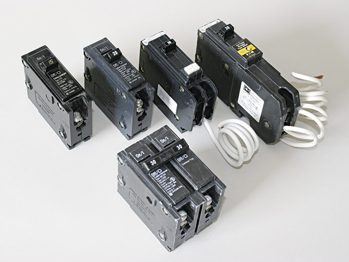
- Two-pole breakers serving 120v/240v or 240v circuits must be correctly phased. That is, the top jaws of a two-pole breaker must clip onto a Phase A bus and the bottom jaws onto a Phase B bus. If you install a bunch of one-pole breakers at the top, two-pole breakers lower down may not land on correct phase-positions on the buses. (The perils of ignoring phasing is discussed above.)
- If you put larger breakers at the top, you will need shorter runs of large-gauge wire to reach those breakers. No. 10AWG and No. 8AWG wire, for example, are stiff, hard to work with, and take up space. If you wire large breakers first—when the panel is relatively empty—you will have more room to wrestle stiff wire into place.
- Snap AFCI and GFCI breakers to buses next, after 120v/240v and 240v breakers are in place. Here, the issue is not the size of wires but the number of them. You must attach neutral wires directly to AFCI and GFCI breakers rather than to neutral buses—which means running neutrals slightly longer distances.
Terminate wires
Your panel layout will determine in part where you attach the wires. In other words, terminate wires on the side they come in, if possible. That’s just common sense. Wires making long loops to get to a bus on the other side take up space. Thus, if you have wires coming down from both sides, it makes most sense to divide wire groups. To facilitate this, panels typically have neutral and ground bus bars on both sides.
Attach grounds first. As noted earlier, it’s customary to first separate out ground wires and terminate them to a ground bus. So if most of your cables enter at the top of a panel, it’s most logical to start at the top of a ground bus bar and work down as you terminate individual wires. In this manner, subsequent wires can come in right over the top of those installed earlier, creating a relatively flat layer.
Bundle wire groups loosely to conserve space but stop strapping bundles just above a bus so you have room to turn wires toward the bus. Take a pair of pliers and turn the first wire toward the bus, noting how long its “leg” must be to reach the bus. Maintain that same length as you terminate subsequent wires, so that all turns are consistent. (Snip excess wire as you go.) That’s just a personal preference: The important detail is tightening down bus screws so that each wire is tightly held.
Attach neutrals to buses, except for neutrals that feed AFCI or GFCI breakers. In a service panel, attach neutrals to a common ground/neutral bus; in a subpanel, attach neutrals to a separate neutral bus. As with grounds, if panel cables come in from the top, start at the top of the neutral bus and work down methodically so subsequent wires will lie flat.
AFCI and GFCI breakers, on the other hand, have factory-attached neutral coils. Attach those coils to a neutral bus. Then terminate circuit-cable neutrals to designated lugs on AFCI or GFCI breakers.
Terminate hots to breakers. As with grounds and neutral wires, move in one direction as you attach hot wires to breakers—typically from top to bottom, if panel feeds enter at the top of the panel. (This will create a flat layer of hot wires with a neat, workmanlike look.) As you did with grounds and neutrals, loosely bundle hot wires till you are ready to start bending them towards breaker lugs. A sweeping bend looks best, so try to maintain that angle for all hot wires as you attach them to breakers on both sides of the panel. Strip 3⁄8 in. to 1⁄2 in. of insulation from the ends of hot wires before inserting them into breaker lugs. This will ensure that breaker screws will tighten down on bare wire.
If you placed larger two-pole breakers at the top of the hot buses, you will attach larger-gauge wires first. The labeled slugs you slipped on the hot wires will tell you which hot wire attaches to which breaker. Correctly matching wire gauge to breaker amps is essential because both will be rated for the loads that circuit will carry. When attaching the two hot wires served by two-pole breakers, electricians typically maintain the A-B phasing established earlier, to match the Phase A (black) and Phase B (red) feeds.
As with all electrical connections, screw breaker lugs tightly on hot wires so there is a solid mechanical connection. This will ensure a good electrical connection.

Excerpted from Wiring Complete, 3rd Edition (The Taunton Press, 2017) by Michael Litchfield and Michael McAlister
Available in the Taunton Store and at Amazon.com.

View Comments
If you are using the right breakers there is no way to get out of phase when installing breakers in a modern panel.
NEC 210.4(B) requires simultaneous disconnection of the two hot wires, meaning that they must be connected to either handle-tie or common internal trip breakers. Thus, the "correct" part of the diagram is not correct because it depicts connection to two independent breakers.
On a more qualitative note, the labels look sloppily lettered, use unhelpful abbreviations, and invite curious fingers to turn them to a correct reading orientation which invites contact with hazardous conductors. It's better to use a diagram pasted to the inside of the hinged door that uses the manufacturer's breaker space designations.
Also, the panel lacks any type of cable stays and instead just relies on the stiffness of the wire itself which is not easy with the stranded conductors used with raceways. And there is no mention of using a torque wrench.
All in all, if I were a pre-publication reviewer, I would vote to not publish this article because it fails to provide the information promised in the title. And I certainly would not purchase the book. It seems that the point of the article is promotion of the book. It is below the standard that I expect of The Taunton Press.