? A different way to attach rafters?
Lets pretend that I am building a 24’ x 24’ building, and I put my ceiling/floor joist on top of my first story walls. Lets pretend next that I sheet the whole floor with ¾ tongue and groove. (The whole thing, all the way out to the rim joist) Now lets say that in my crazy world I screw down a 2 x 4 “rafter plate†atop of the floor decking I just put down. And thus fasten my rafters to said named plate. What do you think- am I crazy? (I know that the ceiling joist lock the bottom of the rafters in place when you nail them together, however, I don’t see the how bottoms of those rafters could spread out with a plate nailed directly to the floor decking with the floor joist directly beneath it. Hope this made sense… just hoping to get some of ideas on whether or not you guys think this would even be code acceptable, and any other comments. thanks
Edited 10/19/2005 7:56 pm ET by paulewog


Replies
What you propose sounds fine to me, but I'm not a building inspector. Seems like what you propose is the same as what most builders do, except that you have added a plywood deck on top of the ceiling joists. I don't really know why you would want to go through the trouble and expense though when the ceiling joists already prevent spreading of the walls and you can just nail them and the rafters to the top plate of the walls.
If you are concerned that the ends of the rafters might slip off of the plate you're screwing to the deck, you could cut "birds' mouths" in them. I would not use screws though to fasten the plate; I would nail it, as nails have more resistence to shearing off and that would be the direction of the forces acting on the fasteners--shearing them rather than trying to pull them out.
Maybe I am missing something. Anyway, I am curious as to why you want to do it this way, as I see no real advantages other than you could have a rim joist that would serve to keep the ceiling joists from twisting. (And you have a floor in the attic.)
I see a fair amount of houses designed exactly as you've described. In some cases it's done to create more room between the soffit and 2nd story windows for large frieze details, other times there doesn't seem to be any apparent reason. We do add hurricane ties when we frame this way as the inspectors want to see them on any rafter that doesn't have a joist sitting next to it.
I like seeing this detail sometimes as it makes it easier for me to frame larger gable in two pieces this way.
Do it all the time.
Just get clearance from your local inspector if the plans were not drawn as such.
Lemme get this straight....
YOU BANNED REZ?!?!
Holy bagels and lox Batman!
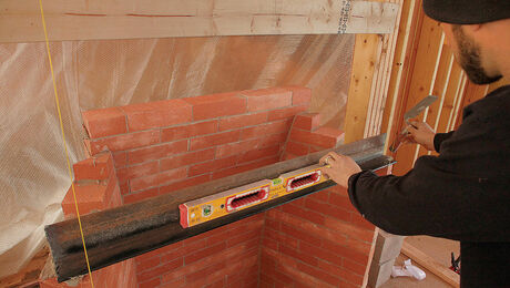
I would say its OK, but I would notch the seat-cut over the 2x4 cleat, as shown in the pic. Otherwise you're relying on a few toenails to counteract the spreading force acting on the rafters. Also, I would use hurricane ties to counter uplift forces.View Image
Good call Huck. I missed that part and just assumed there would be a seat cut.
I guess I should have been a little clearer: I also assumed there would be a seat cut. What I was saying was that I would cut the sea-cut as in my example at the top, not like a standard seat-cut (shown below), where the rafters would tie in with the c.j.'sView Image
I missed that too Huck. Only problem I see is that the inspectors around here don't like to see the heel of the rafter inside of the bearing wall. With a cut like that you've effectively reduced the size of the rafter by the depth of that notch from a span point of view, know what I mean? You've also moved the heel of the rafter off the wall and into the frame.
We do get away with it in tricky spots sometimes. Occasionally we'll need to push a header up into the roof a bit to accomodate a weird situation. Inspector doesn't usually moan if it's just the three or four rafters that land on the header, but that assumes the notch is reasonable. If we have no choice but to make a super deep notch, we usually create a 'flat' at the heel that will accomodate a joist hanger and hang the rafter off the header. I'm not sure I could get a whole roof of heels cut like that to pass.
Yeah, a lot depends on the actual application - i.e. is there a structural ridge supported from below, is there an overhang, if so how wide is it, how steep is the pitch, how deep are the rafters, how smart is the guy cutting the seat cuts. I don't usually do it that way, but I don't usually set my rafters on a cleat atop the sheathing, either. My point was there should be some compensation to address the outward pressure the roof weight puts on the rafters at the plate. Most guys just use a few toenails from rafter to plate, and I don't think that would be adequate by itself.
Now if someone, such as the PE on the project, would come up with a lateral load component....
but, see'ns how we're wingin' it here....
Whenever we plate a sheathed roof or platform for conventional framing extensions from trusses, the plate, single or double, is always lagged into the framing below. No nails, except for positioning. For a plate parallel to the ceiling joists there should be a rim joist out there to lag to, or blocking if you don't think there's enough meat. We're talking locked down here. And, if the platform is new, it will also be strapped in some fashion the the framing below.
Then the rafter is cut, either a scarf or a birdsmouth, depending on which end of the board you're looking at.
Most of the time, even here in the land of our lady of the perpetual hurricane, the ends are toenailed and either an H3 for single plates or an H-2.5 is nailed.
To double the values, the PE sometimes specs doubling the fasteners, one on the inside of the plate and one on the outside - placed diagonally.
One fastener I have yet to use, but see great potential for just the scenerio the original poster detailed, is the Simpson HS24. Although pictured in the catalog applied to a truss, there appears to be no reason why this connector cannot provide the uplift and lateral load protection needed at the birdsmouth of the posters project. Look at the F2 table and compare it to the common H series hurricane ties everybody uses - 1025 vs ? Somebody do the math. How does that compare to the two or three nails most use to lock a rafter to the side of a joist?
This is done all the time. I didn't see you say anything about not putting a birdsmouth on the rafter but you should. There's no reason not too. We have to put hurricane ties nailed to the rafter and the plate here.
This house I just framed is H shaped and had two 30'trusses from side to side in the main section of the house a microlam that sat on top of them for the ridge and the rafters were nailed to that. So the rafters sat above the trusses which raised us above the top plate almost even with the top of the ceiling joists. Those rafters had a pitch of 5-11/16"/12 and the two side roofs had a 7/12 pitch so I had to adjust the plates and birdsmouths a little bit so that all the 2' overhangs lined up.
Once all the rafters were nailed in we nailed hurricane ties on. The only thing with this is you we have a double stepped freeze board with dental molding and crown molding because of the height from the top of the windows to the bottom of the soffits.
Sometimes you have windows that have transoms or circle tops above them and you have to put flush headers in because the top of the window might be 4"-5" down from the bottom of the joists and once you put an overhang on the bottom of the fascia would be to low. Raising the rafters on top of the ceiling on a plate solves this problem.
The first picture if you look in the background you can see the rafters on top of the joists. The whole attic is decked ,so they have plenty of storage and all the subs love it especially the HVAC guy.
What a resource you guys are, thanks to all who replied. I feel much better now. (i had planned on cutting the birds mouth in the rafter) Im not sure if i will go for it or not. It seems very safe to me, depending on your pitch,you might be able to work off off one section of scaffold to nail the rafters to you ridge. Another advantage i thought of is if this proposed roof was a hip, you can run all your joist the same way- you wouldt have to run a double and piece in the rest at 90 degress when you get out towards the edge. anyway thanks again, you guys rock. Semper Fi!
You can do anything you want once the deck is on and you nail your plate down. The only other problem you can run into which I have before is your height requirement. Those ceiling joist I used were 12" I-joists so you raising the roof line 12" plus the decking and the plate so if your tight you might have to lower the pitch of the roof and figuring out exactly where your ridge would be is also easy to do.Joe Carola
Nice pics Joe! Got any more? I see you had a forklift. Are you using one all the time now? Or did you rent it for that job?
The forklift was supplied by the builder. What a blessing this thing was as you already know. If I framed houses all year I would definitely use one but I do more additions then houses.This house was H shaped and the two trusses that we set came from Farmington, NY and they were 30' long and the ridge sat on top of them and are rafters were nailed into the ridge. We had a crane come in the same morning the trusses came in. I had to cut the top point of the teo trusses 3-1/2" level to set the 3-1/2" x 11-7/8" microlam ridges on.The house wasn't hard to frame. All 2x6 walls with 10' ceilings except for where the trusses were I had to make them around 11' so that the bottom of the trusses were even with the top plates of the 10'walls and the bottom of the rafters were 1-3/8" above the trusses and the truuses were 25.36° or 5-11/16"/12 pitch and the two side roofs were 7/12. We had 2' overhangs and I made all the fascia lines even. That's why we sat the side rafters on top of the ceiling joists.Here's some pictures. Nothing to interesting but Joey flexing.....;-)Joe Carola
Here's some more pictures.Joe Carola
Great pics Joe.
One question. Why didn't your use the machine to set the trusses? My only guess is that it won't reach, but it looks like it would reach to me. Of course, I'm not there though!
blue
Thanks Blue.The forklift wouldn't reach. From the edge of the dirt to the center of the room was almost 45'. As far as I know from what the guy who drove the forklift said that is was a small machine.Joe Carola
Edited 10/22/2005 1:28 pm ET by Framer
Is that your forklift Joe? That is the same design as ours, but the 6000lb machine.
Did you build those trusses? They look perfect. Your framing looks good as usual. Who would have thought that framing could become respectable? :-)
I bet you didn't need a forklift to set the trusses. You and little Joey set them by yourselves didn't you?
edit, I didn't see the above posts.
Edited 10/22/2005 4:41 pm ET by Timuhler
General note to all-
W'eve framed a zillion of thes over the years for reasons already written here; more room over windows for frieze detail, bigger windows w/ buried headers, more room above (hey on a 12 pitch room, you gain a foot of width @ your knee wall on both sides the length of the room) etc.
The issue of the connection at the plat is a valid concern, I think. We've always locked them in with 3/4 plywood scabs, 8-10" wide around 3 ft long, nailed w/ 6d (5 or 6 spread out) to the side of the rafter near the bottom, sits almost on top of plate, runs back on a low angle (more flat) and nailed to side of ceiling joist. This does mean sheathing can't go all the way to outside, but it's where the rafter is only 1-2ft above floor anyhow.cut scabs so they end just above bottom edge of ceiling joist. ties it all together great, and keeps the plate from "rolling" or pushing out at all.
my .02
Bing
Colts Neck??!!
I was just working there today, off 34, off Conover Rd.
This sounds like a fine idea and I would expect that in most cases it should be perfectly acceptable. Allow me to answer a few questions that you raise though;
Lapping rafters with the ceiling joists would usually provide a shear connection that has more capacity than the connection you describe. One important qestion would be how much of a connection is really needed. This can be calculated but it would be dependant on a number of factors including, span, loading, slope of rafters etc.
One of the more critical considerations (if not the most critical) would be whether or not the rafters are suported vertically at their top. I think in your case they are not (if I understand your plan correctly) but in the cases of some of the replies, I expect that ridge support is provided. With vertical ridge support there is far less load to contend with at the bottom of the rafters. Most critically, there would be no thrust to content with if the rafters are supported vertically at their tops. In your case there is thrust but it is possible that it is within the safe capacity of the connection you are using. I think it is appropriate to question this condition as there are several factors that affect the magnatude of the thrust that can not be easily determined by visual exam alone.
When you say "vertical support" for the ridge I assume you mean a ridge beam posted down. I've never seen a situation where this was necessary when framing to the deck plates the OP was asking about. Uplift is the main force to contend with when framing in this manner and hurricane ties alleviate that problem.
I believe you'd have to have a mother of a snowload to get the ridge to sag when framing in this manner as the rafter to plate connection would have to fail in shear. This connection is also reinforced with the use of the hurricane ties necessary for resisting uplift as well.
For the most part I think you are right but i don't necessarily agree that uplift is the main concern. I thing thrust is the main concern. Here are some considerations that I would have;
1.The contribution of the hurricane ties would be very slight it seems to me. I know they have lateral capacity but it seems that the way they would ordinarily be installed, it could be very limited. With the plywood floor sheathing in place, they would have to be installed outside of the rim wouldn't they? (Not on the inside like one might do at the top of a wall.)
2.The connection of the plate to the subfloor is affected by several things; Do the nails go thru the plywood and into the joists or are they only penetrating the plywood and missing the joists? What about where the joists are parallel to the exterior wall? Would full depth blocking be utilized? one joist space or more? If not, what mechanism is there to prevent the joists from wanting to roll? I understand that they are not likely to roll but there are limits on the structural value one should consistantly assume for the given set of conditions.
3. The shear capacity of a nail is based only in part on the actual strength of the steel. The failure mechanism is going to be more likely affected by the amount of embedment into the wood and the qualities of the wood. The steel might be plenty strong but if the wood fibers around it crush and displace, the plate will shift outward, possibly to failure.
4.The connection of the rafter to the plate has a finite capacity allowed by the limits for nails (toenails are 2/3 of a regular nail capacity). A notch or birdsmouth as described also might not be as great a feature as one might think. It might not be too difficult to split the notch out if it is only about 1 1/2 inches deep. The design standard for wood (NDS) does not allow any capacity for this notch.
With all that said, I have never seen a plate connection such as the one descibed in the original post fail so most of my interest is academic. I appreciate the insight of those in the real word that is provided in this forum.
Ummmm..... I guess we could micro-disect this scenario, but it doesn't sound like that much fun to be honest. Seems to me that there is pretty much always an obscure situation where pretty much anything in building could fail.
It's an acceptable method of framing in many, maybe even most, situations. I think we both agree on that, right?
I'll answer your questions the best I can though:
1. You're right I think. The hurricane ties would do little to prevent outward thrust of the roof. But like I said.... belt and suspenders. I don't see it going anywhere in the first place. Also, I believe it is the Simpson 2.5's that only need 1 1/2" of surface to nail to for an approved connection. I may have the part # wrong, but with the ties that I'm thinking of, we still install them on the inside of the frame in these situations.
2. Anyone who nails that plate down in the middle of a joist bay instead of into the joists shouldn't be building chicken coops, let alone roof framing. That's framing 101 stuff.
In the situation where a plate runs parallel with the joists below..... well, I was picturing a gable roof, so we wouldn't need to worry about a plate and rafter there. In a hip roof situation, we usually change the direction of the joists and use outrigger joists for the first and last two feet or so of the run to accomodate the rafters. Why change a good thing just because you are relocating the roof vertically another 10" or so? This way you'd still have the joists to nail the plate to. You would have to run a joist at 45 degrees in each of the corners to provide good nailing though.
3. Wood fibers crushing, imbedment depth of the nail, displaced wood fibers........... now we're getting kinda crazy, don't you think?
4. I don't really follow this one. Are you saying that a birdsmouth in a rafter is a bad idea?
I don't think I'm putting too fine a point on things. Overall, I've said that I think this condition would perform adequately in most cases. The question was about what are the factors involved in this detail. I have tried to illuminate the technical points of the question.
To your comments:
1. I have no complaint.
2. No problem with the chicken coop comment either but the omission of such clarifications is often why we have people complaining about the various disparities in pricing and quality. If it's not spelled out, one can interpret it however one wishes and that can lead to vast differences in the final product and price. In the first few posts there was a reference to hip roof so I was thinking about it that way.
3. The wood fiber thing is straight out of the design standard for wood and is the definative method for determining the capacity of nailed connections. I agree it's not alot of fun but IF one has to provide numerical justification, that is how it is done.
4. The notched condition, I think would also qualify as a technical "no no" according to the design standard. Basically if the rafter is thrusting outward, there will be pressure on the notch that would tend to cause splitting of the 1 1/2 inch portion that is adjacent to the plate on the floor.
I have seen tons of old style notched joists that should be prone to splitting but the are not. I suspect that many old buildings are no longer around because they are defective. In any case, the design standard no longer allows notches like this or severly limits their capacity because they are prone to splitting.
One big factor that I think at least partially explains the disparity between how some buildings perform well and the limitations of the actual technical design is the fact that design codes must take into account so many things that could be marginally done. In a well built structure (i.e.very good workmanship) the actual performance is going to be better than one can safely assume in the design.
Thanks again for your comments.
I hope you don't think I was being adversarial. I'm a bit of a nuts and bolts kind of guy and tend to think of situations from a point of view of being out in the field. I guess when a topic gets to a certain technical "line in the sand".... I tune out a bit. My bad.
You raise some valid points. But some of the physics and engineering behind it all is a bit over my head. Welcome to forum, by the way. You seem very well 'spoken' and well versed in construction principles. Fill out your profile when you get a minute so we can all get to know you a little better. What field are you in? I'm going to guess some kind of engineering? Or just a thoughtful carp? Again, welcome to the forum.
Our last house was done as suggested in the original post except with floor trusses instead of lumber joists. The architect specified a number of metal connectors both as hurricane clips and as connectors to the plate/pywood. I had never put in so many connectors in this situation but it was a good rainy day job for a laborer and certainly removes any doubt. I would do it again even if not specified.
As for the real world I have this set up in my own house and have seen it in many other houses with only toe nails for the connection and have never seen any indication of a problem. A few years ago we had two deep (2ft.) wet snows in the spring which caused a number of roofs to collapse. In every case the roofs had ties at the plate where the connection failed. The rafter-collar tie nails deformed or in the case of timber frames the pegs sheared or deformed the wood and the roof inverted when the plates spread. In every case the ties were 8 or more ft apart.
As you so correctly point out, structural design in wood structures needs to account for less than perfect execution. In this case I am guessing that the redundancy of repetitive framing really does the job.
I design that way myuch of the time for added storage space in the upper level or to lift the roof for other reasons. I see it in many older homes too, so it is time-tested.
your poiint about hips roofs is well noted.
BTW, that used to be my nickname on jobs once upon a time Paul E Wog
Welcome to the
Taunton University of Knowledge FHB Campus at Breaktime.
where ...
Excellence is its own reward!