Hello all,
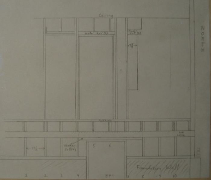
I need some direction on specifying the type of header I need over the basement door since it will now be asked to carry the load from one end of the header I am adding over the kitchen doors. All of this is taking place at the back wall of the house. The drawings best illustrate what I am trying to do. The hand drawing shows the balloon-frame construction with the single 2×8 header over the basement door, behind the 1×6 joist support let-in to the wall studs.
Unless I want a very short basement door, I am stuck with a 2×8 something. I need to propose something to the building department, and that something will probably be a glulam header or a flitch plate sandwiched by a pair of 2x8s.
The building department people have pointed me to the 2000 International Residential Code book. Chapter 16 looks like it is related to what I am doing.
If I am to do a proper engineering design, how can I determine the anticipated loads the header will bear and the resulting deflections?
Thanks,
Scott


Replies
Propose a 2X12 header with a 1/2" plywood flitch plate. $20 in material and it's probably overkill but should certainly satisfy the B.D.
Be sure to add continuous blocking along the path of bearing from the upper header to the lower one and then of course from the lower to the foundation.
Edit to say... I noticed that you only have a single 2x4 running for blocking below the door frame from the upper header... then you show no jack studs from the lower header. For the purpose of better "safe than sorry", I'd double that upper blocking and then use double jack studs for the lower door opening/header support.
http://www.petedraganic.com/
Edited 8/7/2007 2:14 am ET by PeteDraganic
Hi, and thanks for all the replies.
PeteDraganic, I do not have the vertical space for a 12" header above the basement door, unless I use a flush header as Ragnar17 suggested, which does seem like a lot more work. By continuous blocking, do you mean solid jack studs from the kitchen header to the sill plate? Yes, the hand drawing only shows the existing, which has no jack studs on the bmt door header.
Ragnar17, The bmt door header is supporting 3 wall studs and floor joists, so is 62.5" long. While that span is relatively short, it is also supporting one end of the kitchen header, which supports the 4 wall studs above it.
Any idea the cost of such an engineering job? I was assuming it was expensive enough to make me do the math myself. To that end I need to know what the standard dead an live loads are. I assume that the IRC specs lbs/ft^2 based on some estimate, but I could use some direction to where that might be found.
Thanks,
Scott
Use whatever the largest dimension is that will fit. So long as it is not undersized... then other options are needed. What kind of space do you have to fit one in. From the drawing, it seemed like 11.5" would fit.
Yes, by continuous path I mean that there should be a straight path of structural bearing from the ends of the header to the foundation below (on edit: excluding where an opening exists in that path as the new header assumes that load). I don't know if you already accounted for that. I was just commenting on what I saw in the drawing.
http://www.petedraganic.com/
Edited 8/7/2007 4:18 pm ET by PeteDraganic
The distance from the top of the bmt door frame to the bottom of the floor joists is 8".
Due to the compound load, I would be afraid that a 2x8 might be undersized. You might want to add a steel flitch plate.
http://www.petedraganic.com/
Scott,
Do you understand the idea that Piffin and SamT have forwarded? If you make the header on the main floor a little bit longer, it will move the point load away from the basement header.
I think that's the best answer. You'll then have a nice clean load path from the header on the main floor all the way down to your foundation.
Your current hand drawing doesn't show any jack studs (aka trimmers) under the header in the basement; you'll want to add those.
Also, make sure you have squash blocks to transfer the load from under the sub floor of the main level down to the next framing member. Orient the grain of these blocks vertically.
Edited 8/7/2007 7:42 pm ET by Ragnar17
Scott,
I'm assuming your basement door is 36", right? So therefore, the span of this header is only going to be something like 39".
I don't see any reason why a doubled 2x8 wouldn't handle that load. The span is very short, and the span is the primary factor in sizing a beam. For reference, I've got 4-foot spans over the basement windows of my two-story house, and the engineer spec'd those with doubled 2x10s (and for the record, I think that was overkill).
Unfortunately, I doubt the city is going to let you size the beam without some sort of engineering calculations. If that turns out to be the case, the engineer is going to need a lot more information than you've shown in the drawings here.
For example, the engineer will need to know: (1) how much floor area is supported by the floor adjacent to the basement wall in which the door is located, (2) what kinds of loads are coming down from the roof and second floor onto the main floor adjacent to said wall, (3) local building code design specifications for both the live load and the dead load for all floors and the roof, too.
If you just bring your complete plan set to an engineer, he/she will be able to perform some calcs, specify the header, and then the city will pretty much rubber stamp your plan set.
Edit: By the way, if the engineering design calls for a beam that's too deep to allow good headroom at the door, they can always use a "flush beam". That is, the beam will sit directly against/beneath the subfloor, and the joists will tie into it via hangers.
A flush beam will be a lot more work to install, but it will completely eliminate the problem of head room.
Edited 8/7/2007 2:20 am ET by Ragnar17
Not sufficient info to say specificly here, but I have a dual solution/snswer.
First, besaed on what I see, a doubled 2z8 should work OK.
But for extra assurance, there can be a doubled rim in the floor systen immediately above that space to function as a header, and in the wall above, the header in that door can be oversized and extended so that it is longer to spread the upper loads off to the side of that basement door entirely.
Welcome to the
Taunton University of Knowledge FHB Campus at Breaktime.
where ...
Excellence is its own reward!
I thought he stated that the house was balloon-framed. Therefore, no rim joist in a header-like position.
This is why I suggested the overkill use of a 2x12.... because with balloon framing, there is often a constant load path from roof to foundation at each stud location.
http://www.petedraganic.com/
I understood the ballon frame to be from floor to roof, noit into the basement.But he an stil carry this load by oversizing a header up above that door in the main fooor
Welcome to the Taunton University of Knowledge FHB Campus at Breaktime. where ... Excellence is its own reward!
and in the wall above, the header in that door can be oversized and extended so that it is longer to spread the upper loads off to the side of that basement door entirely.
Great idea!
sam drew it too!nothing original about it when you think in terms of total structure and entire load path.
I tend to think globaly a lot, when too often the temptation is to focus too tightly on the immediate problem
Welcome to the Taunton University of Knowledge FHB Campus at Breaktime. where ... Excellence is its own reward!
Sam drew it first, but you described it first; maybe you guys can share the credit.
From the drawings, it looks like the kitchen header will have to be moved to the right by about 15"; that puts the right-hand end right at a wall corner.
Do you think it would be possible for the OP to keep the short stub wall where it is now, or would it just have to be eliminated? What I'm having a hard time envisioning is whether a "non-bearing" stub wall could be located under the lengthened header WITHOUT acting as a load path.
"whether a "non-bearing" stub wall could be located under the lengthened header WITHOUT acting as a load path."Yes.As soon as the stub wall picks up the least amount of load and deflects any at all, the header transfers the rest of it to the all-the-way-to-the-foundation load path.IOW, the proper load path has to fail before the sub wall becomes a true bearing path.SamT
Edited 8/7/2007 10:39 pm by SamT
As soon as the stub wall picks up the least amount of load and deflects any at all, the header transfers the rest of it to the all-the-way-to-the-foundation load path.
Thanks -- that explanation makes sense.
Master **PIFFIN** gets all the credit. I didn't even look at the pictures till he talked about the solution, and I saw that there was some misunderstanding.Duck, run, and cover!SamT
I hereby rescind all of my praise and bestow it upon Piffin.
http://www.petedraganic.com/
now I'm going to have a hard time walking around today with my head all ballooned up.
Welcome to the Taunton University of Knowledge FHB Campus at Breaktime. where ... Excellence is its own reward!
Bmnt current load shows the load the header has to carry as per your plans. Inside the red line.
Bmnt new shows what everyone is saying. A longer header plus two studs (in red) takes all that load off the header and just leaves the load in the green. . . circle? loop? outline?
SamT
Sam,
That's a brilliant solution. I should have thought of that... LOL.
Life Piffin said, sometimes we focus so tightly on the problem we don't see the fix... or words to that effect.
That certainly improves the situation for a smaller header in the lower opening.
Not to mention that he'll surely impress the building department with the flash of brilliance. Next, they'll be coming to HIM for advice.
http://www.petedraganic.com/
The hand drawing only shows the existing framing, and only what I can visually verify.
The kitchen header is being expanded to cover both kitchen doors, openning up that wall. This is shown in FloorPlanAfter.first.pdf. I need a pair of 2x10s with doubled jack studs to support each end. If I terminate the north end of that header at the stud labelled 7, then I am still transferring load down to the bmt header, but at the point where the bmt door frame supports the header. I don't think the 2x4 bmt door frame is as important a support for that header as the ends at studs 4 and 8. Terminating at stud 7 also means I have headers running continuously from stud 2 to stud 7, leaving me nowhere to run the electrical for the outlet and kitchen light switch shown between studs 6.5 and 7 (the BX runs from the switch up to the ceiling. The only way to terminate the north end of the kitchen header to be clear of the bmt header is to go out to stud 8, but that stud is itself interrupted by the window header going from stud 7 to (probably) stud 10.
I think that terminating the north end of the kitchen header at stud 6.5 (north door frame stud) would place the load nearly centered on the bmt header, giving a near even distribution of load between that header's supports at studs 4 and 8. It would also allow me to keep the existing electrical.
Ragnar17, I do not understand the squash blocks. Are these added on top of the sill plate?
A doubled 2x header has 1/2" between the two 2x's. One normally puts a 1/2 ply spacer there. Leave 4" of the spacer out where you need to run your wire.Imagine for a moment that the basement door frame isn't there. Now you need to have double Jack studs from the upper header all the way down to the foundation, including in and around the floor joists, at #2, #4, and #7. OK, now put the basement door frame back in.FYI, the jacks under the header, next to the door are called King studs. The Jacks in and around the floor joists are Squash Blocks. The door frame studs at #6.5, will be Trimmer Studs. Other Jacks are Jacks. Balloon stud #2 needs to be cut and replaced with Kings, I would size the header to run to stud #1 and sister one King to #1. The Kings at #7 can be sistered to #7. And that makes the door frame studs at#2, Trimmers. If you only use one Trimmer, and it is not sistered to a King, you will need to put a block in the center across to the next stud for stiffness.If you intend to trim those two side by side doors, you need to figure enough distance between them for the trim. That spacer can be another King stud. I am imagining that in your house, turning the spacer sideways will look best. Then it would be a Face Stud. Be aware that when a vertical load path is interrupted by a plate, the stud under the plate can be offset horizontally from the upper stud by the thickness of the plate(s). You should try to avoid accumulating the offsets.SamT
Edited 8/8/2007 12:54 pm by SamT