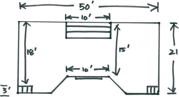
I’m trying to work out the proper placement for the Glulam supports for the deck. I tried a couple of different deck design programs and both were garbage.
I figured one across the middle, two on the far end (one on each side of the stairs) with a foot or so cantilever, and one in front of the stairs (the width of the stairs).
I’m not quite sure how to handle the support for the recessed stairs against the house on each side.
Can any of you deck masters give me suggestions? I apologize for the sketch, I build better than I draw 🙂
Thanks
Mick


Replies
Did I stump you all? :)
Mick
How far does that bay protrude?How much is the inset for the 10' wide stairs? Three treads as shown? What size treads? They go down and not up, right?
Welcome to the Taunton University of Knowledge FHB Campus at Breaktime. where ... Excellence is its own reward!
I had seen this - too late at night to think that hard, I guess.
Who came up with the stair placements?
The whole thing seems cumbersome to me.
What about height and the grade below it?
What kind of framing?
And why glulams?
Is there a need to limit number of posts and piers?
Got a photo of the site?
Welcome to the
Taunton University of Knowledge FHB Campus at Breaktime.
where ...
Excellence is its own reward!
I was just bustin' chops Piffin, I knew someone would respond :)
Customer dictated layout and the recessed stairs, yes I agree, cumbersome.
Deck will sit around 36" above grade. Pretty flat surface. No, not a need to limit post or piers other than less digging holes for me, this is a "solo act" so the least amount of footings the better. (But I do not mean to compromise the integrity of the support system by saying that)
Framing is Doug Fur 2x10's. As far as the beams, I thought it would be easier to set solid timbers rather than sandwhich 55' of 2x10's together.
No I don't have any pix of the site, digital cam on the brink unfortunately.
The bumpout is a sliding door and the two sides are not equal lengths as it extends to the back wall, one side angles back around 9' and the other about 5'.
I originally was going to run (4) 6"x10" "glulam type" of beams straight out from the house add supports in the middle areas where necessary and "hang" all my joists, which would have eliminated many footings and still be well supported, but a change in the railing system put a wrench in that gear. I'm still undecided if I want to keep this same approach and use smaller width support beams and more footings or run the support beams as in the "incredibly artistic" sketch I attached and have even more footings.
I imagine if I end up running support beams as in attachment, I would need the support beams as I mentioned, and for the support for the stairs up against the house, I figure I would need to run a support under the outer side of the stairs across (parallell) to back to the ledger (which would be on the part of the wall that angles back).
Mick
I would run two of them the long way. The first would be 7'3" out from the wall, and the second would be 7'3" from that. Each of these would be supported by seven posts 7'3" apart. Obviously, you wind up with a little cantilever in both directions.
grpphoto,
Don't see how that could work.
One, out long ways 7'3" would work wouldn't present a problem, but the second one 7'3' from that, would run "through" the opening of the recessed stairs.
Also, by doing it the way you suggest I wouldn't have any support for the opening of the recessed stairs against the house at the back.
Your thoughts?
Mick
You run your joists perpendicular to the house. The deck next to those stairs by the house are supported on two beams. That's plenty of support. The top of the stairs is sitting on a joist that is attached to the house ledger at one end, and is supported by two beams further out, with about a 3.5' cantilever at the outside edge. Got some photos of an identical stair situation, but I'd have to locate and scan them in (they date from about 1992).If that outer beam will interfere with the outer stair, though, there's no way around it. What you would have to do is run the outer beam at the location I prescribed on both sides of the stairway, and run another beam closer to the house at the top of the stairs. That one would be only a little longer than the width of the stairs.George Patterson
Would appreciate those photos if you could locate them. Thanks, man.
Will get back online tomorrow to discuss your post. Can't seem to keep my eyes open tonite.
Mick
Just a quick concept. Probably not the cheapest approach but I've never been accused of underbuilding decks. Decking ought to run perpendicular to the house to ensure good water run-off.
I don't like to cantilever more than 2' but maybe adjust in this case to make the side stair framing easier. As it is in the pic the side stair openings will need to be headered at the side and a support on the house side of the joist at the top of the stair. Supports can be 2' from either end of the girder leaving a span of 14' at the most to be divided as you feel best with posts. Girders in green & joists in white.
That's about what I had rolling around the back of my head. Thanks for drawing it for me.;)
Welcome to the Taunton University of Knowledge FHB Campus at Breaktime. where ... Excellence is its own reward!
No problem. You think it & I'll draw it.
John,
Thanks for taking the time to put together that diagram.
I understand the reason for running decking out from the house, but customer is set on having it run parallell to the house, so that can't be changed.
BTW, those two attachments are identical right? They came up kind of big so I'm not sure if I could see the entire diagram to compare both. What software do you use? It looks great, unlike the ones I've tried.
Any other ideas?
Mick
You're welcome. Yes, somehow I uploaded the pic 2x; that's what happens when I post in the middle of the night. The 2d pic is only of 1/2 of the deck with the other 1/2 being mirrored. It took about 15 minutes while I sat up wondering what to do about the nieghbors whining/barking dog.
The software is free at Google. Search for Google Sketchup. There is a a purchase version that increases print options and other useful features but the free works for me for now. It'll take a bit of customizing (I made my own lumberyard to use in the models so it's organized in a manner that I can use it easily) but it's not to much of a learning curve (for me at least). You still have to have access to span tables and such but SU helps the idea form clearer. Search the archives here and you'll find more than a few re: Sketchup. If you want I can upload the 3d model for you to try in SU. It's in the PC at the home office so can't upload now.
I'd try to figure a way to get the customer to change their minds regarding the running of the decking parallel to the house. Perpindicular will be easier to hide butt joints (fewer too) in the deck boards, more apealing to the eye (from my perspective), probably less rot issues.
John,
Found the SketchUp download, looks really neat, can't wait to figure it out. Very professional looking from the attachments you included in your post. Unlike my "cheesy" sketch :)
I'm attaching a better drawing that has the exact measurements, which I should have taken the time to do originally, that first "quick sketch" was not accurate and I apologize, I certainly don't mean to waste anybodys time that is trying to help "me". I'll take my cyber spanking like a man :)
Now, on to bussiness.
I attached a sketch with more precise measurements as I mentioned, and I added in my thoughts on how to run the support beams and place the footings.
Footings will be 10". Posts 6x6 set on post anchors. Support beams double 2x10, joists 2x10.
Your thoughts appreciated, and thanks again for software info.
BTW, If the right side of the scan gets pinched off, the measurement from the end of the deck back to the house is 19' (2' shorter than the other side)
Mick
That's pretty close to what I was coming up but for 1 thing. I wouldn't use a ledger attache to the house, I'd make it free standing. To do the ledger correctly the time you spend flashing & bolting correctly would be about the same to build a girder parallel to the house and the details for the girder are easier to do and do correctly. You may have to place an extra post for the side stairs though but that wouldn't be a controlling factor for me not to make it free standing.
Any particular reason to use 6x6 instead of 4x4 for the posts? 4x4 would be more than sufficient for this deck.
Your post spacing looks good, especially with the shorter spans at the edge away from the house where people tend to congregate. 1 thing that occurred to me when laying it out this way after the ledger is built the joists will be 12' or shorter which, in this area, tend to be a slightly better price/LF.
Re: SU From the help menu print the Quick Ref card and learn the keyboard shortcuts (or make your own if you'd like).
Go through all the free tutorials that SU has to get familiar with how to make different shapes.
I uploaded the model for your deck. For detail drawings like this one was becoming I use all premade components form the component library. I've made my own for the most common stuff and organized to fit my thought process. Using components for repetitive use items keeps the file size small and doesn't't burden your PC's RAM. To find the component library go to [Window][Component]. While you're there you'll see a few other menus that will help you such as Entity info (also available from Rt clicking an item), Materials, & Layers. They act like roll-up windows so you can leave them open & out of the way for quick access. You can dock them on top of each other so they stay in view when others are opened.
I try to work in Layers to help organize the views easier. In the your deck model Layer 0 is the plan (which I hadn't updated to your most recent dimensions). Layer 1 is the original idea I had. Layer 2 is the Most recent orientation of the girders& joists. Turn layers On/Off in the Layer menu with the check mark under the Visible column. The radio button (dot) shows the layer you're working in. Getting use to working in layers will be confusing at the start (forgetting to change to the appropriate layer, working in the wrong layer, etc) but it makes for easier organization of thoughts and once you get into larger models that begin to load up your PC's Video Card, tuning off layers lightens the load.
You can change the layer of a particular component on the Entity Window once the item has been selected.
Have fun & don't get addicted to SU.
1 more thing, ther'es ome very cool plug-ins avaialble (more free stuff) on the web. Some of the mosre useful ones for me are Angualr Dimesion (shows the angle in degrees of 2 intersecting lines. Comp Report gives a lsit of all the components in a model (works best when you build with componentns). Cut Lsit I'm jsut starting to sue and also works best when you build with components.
Edited 6/13/2009 2:30 pm ET by john7g
Interesting thoughts on the ledger John, I'll have to kick that one around. as for the 6x6 posts, the 4x4's always seem like little twigs compared to the 6x6's, but I like that they give me a little extra width when setting the support beams in case my post anchors are not lined up perfect.
John you mentioned the joists being 12' or shorter, the only spot that is less than 12' is from the slider straight out to the steps. I originally was going to run full lengths from 22' to 16', but I have a hard time paying the price for the 20'-22' pcs. What are your thoughts?
Really appreciate the SU download and info. Yeah, I can see what you mean about getting addicted to it, can't wait to get at it this weekend.
Mick
Break the joists over the center girder. Max depth of the deck in your drawings was 21'. With the girder down the middle you can use 10' & 12' joists.
Re the ledger: avoid it all costs IMO. It's not worth the addl headache of flashing and hoping you did it right. To flash correctly you'll need to pull siding for access. To attach the ledger you'll need to remove siding so the ledger abuts the rim of the house floor (ie. ledger goes in place of the siding peices. Placing the ledger against existing house siding is a bad plan. Rot & water damage a few years down the road will tell you did it wrong and that'll cost $$$ with the extra headache of a deck in the way while you try to do the repairs. Make it free-standing w/no ledger you leave the original house envelope intact and the decks stands by itself & no worries about water damage to the house; no worries about the ability of the bolts through the ledger into the rim via siding and sheathing/r-board to hold up the ledger & the people above it.
For placing your footings using 4x4s for posts. Set the girders in place using the end posts/footings only and brace as necessary along the length to ensure striaght & level. Locate your footings using the properly positioned girder. (Assuming your using a post hole digger Vs a powered auger.) Dig your wholes and set the 'crete. Hole digging is slightly challnged by the location of the girder but the result is worth it. You can also just run a string between batter boards and do it the old fashioned way as well. Drop a plumb line from the girder to locate the foot bracket for the post.
Did I mention don't use a ledger & go free-standing?
Your posts & girders are your foundation. Do this right and the rest will flow smoother. Do it wrong and...
John,
Good idea to break the joists over the girder, that will save me some coins going with shorter lengths.
What is a good amount of length to run joists over girder when breaking them in the middle like that? Meaning how far over the girder should each end protrude? This obviously would result in each side being offset 1.5" correct?
I hear what you are saying about the ledger. I removed the siding already in preperation of doing a thorough flashing job. Do you really feel that a ledger cannot adequately be done this way? I totally agree with what you are saying on how a free standing deck would shed the water better.
I have several books by supposedly very reputable deck builders and every single deck they show photos of them building, they have attached the ledger to the house. Not one shot of a deck being done the way you mentioned, go figure.
Mick
Joists over girder: No need for anything more than 100% coverage onto the girder. Take the joist just to flush is all that you need. A an inch or so more will help prevent cracking when you nail the two joists together over the girder. Shorter joists saves $$ but most importantly reduces back injuries.
The offset is correct. On the layout make 1 side shorter spacing and the rest will fall on your spacing. Basically a joist on either side of the layout mark.
Maybe I'm not reputable? :0 I know there's a lot of people that still use ledgers but I think they haven't paid attention to the news too much. Search the newspapers for collapsed deck and you'll find a ledger as the beginning of the accident chain. If you make it freestanding it's very easy to ensure correct construction. For fun start a new thread here asking if a deck should be free standing or attached to a ledger on the house framing. Get some popcorn & a fresh drink and enjoy the reading/fireworks. I won't go so far as saying that I'd never use a ledger but I'd not use it for primary load carrying but more so in the case of a 2nd story deck I'd use the ledger to stabilize but still build it freestanding.
Making your ledger connection correct requires that you:
use hardware compatible with the PT wood. You should be considering this already for the other hardware for your deck. ACQ has a bad rep for eating up steel.
use the proper sizing of hardware 1/2" or greater is good
Proper quantity of hardware & correct spacing. Don't use lag bolts. Don't use lag bolts. Carriage bolts or regular hex head bolts with large dia washers will work. Don't use lag bolts.
Next the rim joists needs to be checked for proper connection to the sill plate. It probably is but it doesn't hurt to check now.
Flashing will require 1 or 2 pieces depending on what's below. If there's siding or something other than an un-sided foundation you'll need 2 pieces, 1 under the ledger with a lip over the top of the siding below that will continue up above the ledger in the event any water does get behind it, then another above the ledger to act as the primary water proofing.
Did I mention Don't use lag bolts?
You gonna take pictures of this project?
Edit to add. did you get roped into Sketchup yet?
Edited 10/13/2007 11:18 pm ET by john7g
So basically you are saying "Don't use lag bolts" ? :)
Yeah, plan on shooting some pix along the way, waiting to get my digital back.
I'm itching to get at SketchUp, got jammed up yesterday and am now trying to get through payin' bills so I can grab my laptop and give it a go.
Mick
I'll wade into the ledger debate.
Compared to other flashing details commonly found on houses, there is nothing inherently complicated about flashing a ledger. It takes a bit of thought, but it is something any competent builder should be able to handle. Past threads on this topic have included the way other builders on the forum do so.
If you do decide to make the deck freestanding, remember by removing the connection to the house you have removed the shear support that keeps the deck upright. It now has to be braced against horizontal movement. It also takes a bit of thought to make these diagonal members fit in with the deck and not look like temporary bracing.
The house siding you avoid disturbing by placing the deck several inches away is now inaccessible for maintenance and repairs.
From time to time some element of the building comes under scrutiny because of excessive failures. You have to decide whether these are due to the use of the element itself, or whether they simply need more attention by the builder during installation - which they have not been getting. My take on ledgers is that it is usually the latter.
Anyone have any thoughts on flashing a ledger properly?
I would like to weigh both sides of the issue.
I originally had planned on setting the ledger on the house.
John brought up some interesting points in his previuos posts.
Fingersandtoes also makes a good point with lateral bracing and losing acces to siding for future repair etc...
Interested in hearing opposing views, if anyone would like to chime in.
Mick
You might want to try an Advanced Search. I remember some interesting discussion on both sides of the issue. It really is one of those Plywood vs OSB type things where both sides seem to have an equal number of supporters.
Yes, I have been reading some threads I found in the archives.
Your right, seems like support for each side.
My main concern on the flashing issue is that my deck runs out from right under the door when you walk out on the deck. So i'm trying to figure the best way to flash these areas where the deck planks are right under the door. Not my choice, but it's not my deck either.
Mick
It's going to be tough to flash the door threshold correctly without removing the whole door frame or somehow getting the flashing under the threshold. It may already be flashed from the initial construction. Is there any there now?
For ledgers I follow what's in the attached pic. The lower flashing (#1/blue) isn't necessary if there's no siding below your ledger. Depending on what's used for the ledger 2 pieces of flashing (1 Z-type and Flat flashing) may be needed to get enough behind the ledger. Both pieces of flashing go behind the house wrap if there is any.
Thanks for posting pix grpphoto.
John, yes there is flashing under the doorways, its wrapped over the sill plate and door sits on top of it.
Nice illustration on the flashing attachment. You've got that SketchUp software down huh?
Being that the deck boards are running out level with the doorways, there will be about an 1 1/8" space between the ledger and the bottom of the door before I lay the deck planks. I imagine I will have to notch out the Z flashing under the doors. Would this be a correct way to handle these areas? Should the notched area be siliconed under the lip of the doorways?
On a side note, just a couple of quick questions.
For the gravel base for the footings I was wondering which type I should use based on what the "Depot" stocks (being that they are right next door).
They have a bunch of different stones, peebles, pea gravel etc...
I saw an All Purpose Stone, kind of like little rocks an inch or two each. Would this be a good choice?
Also, I was looking through some of my deck books at footings and I noticed some of the footings (the cement) in the pictures looked light colored and very smooth, and others looked a bit darker and kind of rough. Would this be from the way it was smoothed over possibly, or different types of concrete?
What is the best concrete to use for footings from the "Depot"? I like that smooth looking consistency over that rough look. Like I said, I don't know if that is just the finishing technique or what.
Mick
Notching the Z-flashing is the way to go. It should go closest to the house under existing flashing. If it's under the existing flashing there probably is no need for any caulk/sealant. Seems like there will still be a portion of vertical leg of the Z that can slip behind the door flashing.
I'm the worng person to ask for the concrete questions. Since I learned that GA clay will act like concrete I haven't cemented a deck post. Concrete or gravel (the 1" - 2" variety) poured in the bottom makes the footing, set the post in whole & then fill & pack (with a 12# sledge using the handle to poke and the head in my hand, compacts pretty good) nearly all of the excavated dirt back into the whole. I do know you can make it as smooth as you want. Avoid making it perfectly level so water will run-off.
The SU pictures I had already. When I do hire labor to help me English is usually their 2nd language, sometimes barely or not at all. They usually have some experience but I've found that in some aspect no one has taken the time to show them the right way (or at least my way) to do the work. Their willing to work and very interested to learn so the pics really are worth a 1000 words. Often I'm printing extra copies so they can take them with them.
Maybe someone else can chime in for the 'crete questions?
Stopped at the newly opened HD and they are well stocked with a lot of stuff all the others don't offer.
Found an all purpose gravel for the footings. If the others would have carried this I would have just picked that up and wouldn't have posted on it.
Am going to go with the Sakrete 5000 for the footings.
Mick
whatcha you gonna do for a rail?
The HD concrete I use for footings is the regular Sakrete or Qwikcrete they sell. They have 80lb sacks. If I remember correctly, each is about 1/3 of a cubic foot, so it takes a bit. The last time I did this, I had six footings to do. I drove over to HD, bought the concrete, and rented one of their trucks to haul it all to the jobsite. I offloaded the concrete, drove back, rented one of their mixers, and hauled that back in my truck.The mixer could handle two sacks at a time. I used a riding mower pulling a lawn trailer to get the concrete from the curb to the back yard. Whatever works.If you want a smooth finish, use a plasterer's trowel to smooth out the surface. Working with it a bit will massage any aggregate below the surface of the concrete and give you a smooth surface. The color of the finished product will depend on the sand and aggregate used for that particular batch. It's sort of out of your control. I've seen it set up tan, gray, or almost white. Concrete provided by a local mixer will be more consistent, since they generally use the same local materials for each batch.George Patterson
I'll sencond the motion for electirc mixers I've seen alhtough I haven't used one.
The one's I've seen have wheels on them so you can move the mixed load a little if your chord is too short. Or they can be set in the back of a PU truck and worked from there and then poured into a wheel barrow. Lot's of ideas came to mind when I 1st saw them.
Hey Guys,
Thanks for chiming in as always.
I picked up Sakrete 5000 today and got 12 footings poured, Had the Depot drop a skid in the back of my truck. Bought a hand truck. Dropped the cement off at the job, went back to the depot and rented a 2 bag mixer. I'm hoping to finish pouring the last 10 footings tomorrow, hopefully the rain in the forecast will not show up. I would like to get the rest of the footings done so it can set up over the weekend and keep me on schedule.
I'm a little concerned about something though.
I set all my tubes level, dead on both ways. Set a nice base of gravel and tamped down. Mixed the concrete by the book. Consistency was great. I poured the footings, troweled them off, loooked great (even nice and smooth like I inquired about).
I noticed awhile later that some (not all) of the footings seemed to settle a little lower than the top of the tubes. It was hard to tell if they were still level across the top. I busted my #### to make everything nice and level, I'll really be bummed if they settled off.
My concern is, if they're not perfectly level once dry is this 'gonna make my life miserable when I set the post anchors and set in the support posts to mark them for level?
BTW John, I will be installing a cable rail system. Pretty cool stuff, All aluminum rails, sandwhiched between the joists and bolted through. Continuous cables run all the way from end post to end post.
Mick.
what kind of post anchors are you using?
no rain here although the forecasts was for storms.
I actually should have said the post base anchor, I think.
I set "j" anchors in the concrete, and will be using the 4x4 post base anchors that stand off the footing and get bolted to the j anchor.
Am I using the right terminology? Is the piece that bolts to the j anchor (that the post sits in) also called a post "anchor"?
The ones the Depot carry, I think they are Simpson brand
Are the anchors you're using the ones found on pg 46 & 47 at http://www.strongtie.com/literature/c-2007.html?source=hpnav ?
J-bolt aka anchor bolt.
There's 2 places in life, Perfectly Level and Level Enough. Chances are that if you're not in PL category you're in LE. I'd think that any variation can be made up when you set the post into the anchor. Worst case could be a little time with an angle grinder with masonry wheel if you'd like but I'd really doubt it'll effect you unless it's way off level.
Yes, the ABA44 is the one on page 46.
And yes grpphoto, I will be cutting the posts long and setting them in the anchors (ABA44). Then Im going to hit them all with the laser (I have a fixed point on the house for reference throughuot the job) and cut them to size.
John, what do you mean by any variation can be made up when I set the post? Do you mean level it then? If so, then wouldn't that cause the base of the post to not be flush with the anchor base?
That's basically my concern. That if I have to move the post one way or another to make level, that post won't be flush with anchor base.
I understand what your saying about perfectly level and level enough. I always strive for perfection and sometimes I beat myself up If I don't feel it is.
I might get back there tomorrow and they're fine. But I'm just trying to think ahead, in case it is something I need to deal with.
>what do you mean by any variation can be made up when I set the post? Do you mean level it then? If so, then wouldn't that cause the base of the post to not be flush with the anchor base?<
A little out of level will not be cause for worry, if necessary you can cut the post to match the base. I'd think there's be some way to shim the post anchors too. I don't think Simpson makes shims specifially for this but I'd think towards using some of their other clips of similar corrosion treatment but least expensive.
>I always strive for perfection <
You're not alone in that world. Lot's of us go the extra mile to satisfy ourselves in ways the client will never appreciate. In some manners, such as building a good foundation to a project, it's well worth it.
I agree John.
Footings are done, rain was a hassle on and off all day.
I have all the footings covered with garbage bags. Rain really let loose as I was finishing up.
I'm itching to get back on Monday to check the levels on all the footings. It's 'gonna make me nuts until I know there all good :)
Hopefully I won't need any shims.
After going back and forth with the ledger deal, I am going to attach to house. (I can hear you screamin') I will take the time to flash it well.
Does Lowes or HD carry ledger flashing? Or will I need to get that somewhere else. Do you know the lentghs it comes in?
The ledger won't have any siding below it, so I will not have to use the double flashing technique, correct?
The vinyl siding is removed for the ledger, there is that styrofoam insulation on the house, looks like about 3/4"- 1" thick. I should remove that right? Looks like there is Tyvek underneath that. If not, should I apply new Tyvek or some type of membrane?
Mick
You should be able to find some kind of flashing at the big boxes but I usually get mine from my local lumber yard. Some of the flashing you may have to make up from flat stock.
Re: double flashing, I've not used it in applications similar to yours in the past but I was reading over at http://www.apawood.org/bbh_walls.cfm that there ought to be some kind of weather resistive barrier behind the ledger. The APA site is free but you have to sign-on to get access to their .pdf's. Well worth the trouble (almost none) to sign up.
The styrofoam will have to come off for the ledger and CDX ply of equal thickness will have to be put in it's place. Probably best to make the cut behind the piece of siding above the top of the ledger. Not sure about the location of the Tyvek as you describe it. Here it's on the outside of the insul-board. Where are you anyway? Local climate may have the vapor barrier inside the insul-board but I don't know, doesn't make sense to me as described in your post. As for applying a new membrane it's not needed for the ledger.
I know you've already made your decision based on what you're seeing and what you know but the vinyl siding would've been the factor that would've made it easy to opt for the free standing due to no maintenance issues on the siding. :) (I just had to throw that in there.)
So I made a little pic for you using what the addl info from the APA showing what I think it should look like when you're done.
Edit to add: might be good to put a bead of caulk/sealant at the top edge of the upper flat flashing to prevent any water from getting between it and the insul-board.
Edited 10/20/2007 9:15 am ET by john7g
Thanks for link.
How do I go about making up my own stock? is there a way to make the bends without having a "break"?
Also, what would be a good approach on flashing the 22.5 inside and outside corners?
< Not sure about the location of the Tyvek as you describe it >
The house was wrapped in Tyvek. Siding guys came in and put on styrofoam and vinyl siding.
< I know you've already made your decision based on what you're seeing and what you know but the vinyl siding would've been the factor that would've made it easy to opt for the free standing due to no maintenance issues on the siding. :) (I just had to throw that in there.) >
I hear ya' :)
As usual awesome attachment.
BTW, I'm in NY
Ok, I think I'm getting the picture. The vinyl was installed as an improvement to an older house? Any case, you don't want any compressible material between the ledger and the rim joists of the house. It may be that you can just cut the foam and attach to what lies beneath. What is under there?
Did the big boxes not have the flashing?
There's a couple of different approaches to making the Z-flashing. For me each involves a pounding block I have made from a section of 4x4. 1 of the long edges I routed with a 1/4"r the opposite corner I cut a 45* with the table saw. (another pic for ya).
After the ledger is installed start with nailing the flat flashing to the ledger along what will become the lower leg of the Z-flashing. Nail it fairly often; roofing nails would be OK. Snap lines on the ledger to aid in getting the flat stock nailed on straight and consistent. Make some calcs to locate this line so that you'll have a satisfactory amount of flashing left for the upper leg to be useful (all depends on the width of your flashing). Use the block to start forming the Z, push by hand at 1st and working up to a small sledge. If it's not obvious the radiused corner goes into the corner of the Z you're making. Might want to be sure there's no fancy wall hangings on the other side of the wall since the pounding may unhook a few things. It doesn't take a hard hit but lots of medium hits working back & forth along the length. Focus on avoiding folds other than the ones making the Z. It's not a pretty process but the end result is usually pretty effective.
Yes, I plan on just cutting the foam and attaching to what lies beneath. Like I mentioned, under the foam board is Tyvek over the sheathing.
Haven't checked on the flashing yet, am going to head over to the big boxes this PM.
Excellent idea on the block.
Do you leave the lower leg of the Z flashing nailed, and set the joists right up to it?
I would imagine just a small roofing nail would be necessary?
What size flat flashing would you suggest would be appropriate for making the Z ?
A roll of 12" flashing is pretty handy for just about everything.
Rain has been killing me, but managed to get all the posts installed and leveled. Most of the girders are in and hopefully will be able to finish the last two girders tomorrow.
Just trying to think ahead here.
What would be the best way to insure that deck planks end flush with the two sets of stairs on the sides? (running parallel to the house) The two sets of stairs are at different distances on each side from the end joist.
Once the girders are finished, I'm going to set the perimeter joists on top and square up the entire perimeter. I'm just trying to figure the best way to account for the deck planks ending parallel with the stair opening, and not ending upwith a plank sticking out over the opening or coming up short.
I hope I am explaining this clearly.
Mick
Was wondering how things were going. How did the flashing go? PITA?
If I'm understanding your question correctly you want to to get the decking spaced out so that the boards running the length of the deck fall out so there will be a full board at the the edge of the stair cutout. Right? Kinda like the example in the picture? Full board adjacent to the stair run cut out?
It might be tricky. You're gonna have to determine the difference in the 2 stair runs. Lay out where the decking will fall on from the edge of the stair to get a straight run past the wall with the SG Door in it. Run a line from there parallel to the house to the other end of the deck and pull measurements from there.
Divide that dimensions by the width+spacing of your deck boards. Odds are it won't work out to be a whole number. If it's close you might be able to adjust the decking spacing a little to compensate but be careful not to get too wide of a gap since it'll grow as it dries & wide gaps are not fun to look at. Narrower is better than wider.
For spacing, if they're wet I use 0" to no more than 1/8". The tighter the better. Latley I've been leaning towards the composites due to their stability but i've only a little experience with them.
Did that help?
Cheers
Flashing went well. I found some flexible corners but they were garbage, so I just made my own. I think it should be fine.
Yes, you are understanding me correctly.
I was kind of thinking along the same lines. Using the sliding door wall as a reference. Yeah, I think it will be tricky.
In case I didn't mention it, I am using a composite on the decking. TimberTech.
Looks like rain AGAIN!!!!!!!
Glad the flashing went well; never had to verbalize/put in print those instructions before.
I haven't used Timbertech but I've used some other comps that I've had good luck with on a few experiments. First off, it'll void your warranty if you follow anything I suggest with the comps but I've had great luck rabbeting the edges and installing them tight to each other to have no void, more like a negative void with the overlap. I did however install them at the hottest time of the year when the boards were at max expansion for this climate, ~100F. My own tests showed a 3/32" growth in width between 20F & 115F so this has to be compensated for in some manner. So with that in mind I'd look at how the gap comes into play when laying. I think you'll be very happy with the comp decking although there will be people who don't care for it.
Embrace the rain, you could be in the situation we're in here in N GA with drought Fortunate for me I can hook the well into the house with little effort if need be. I'm definitely the minority in this matter.
Interesting.....rabitting the butt joints. I like that.
If I were to not go that route, what is a good plan for staggering the joints? is there a certain pattern (s) that should be followed, or should repetitive patterns be avoided altogether?
P.S. I'll talk to the weatherman about sending all this rain your way :)
Remember that when you rabbet you're voiding the warranty, so if this is for a client, you are taking on the financial responsibility of the warranty if anything were to come up later. In the situations where I've rabbeted (I rabbetted the long edges) they've been on my own, I doubt I'd ever do it for clients.
Staggering the joints is something that is kind of driven by each deck but also up to personal preference. You probably know that as far apart as the butt joints can be the easier they are to hide, but I also think consistent patterns are more pleasing to the eye than willy-nilly. A progressive step, where a butt occurs at successive joists looks ok, but that can be broke up by reversing the decking cuts on every other row so that the pattern alternates from left to right.
The pic shows the successive butt joint pattern as well as the staggered like the 2nd idea. I used pink to get the butt joints to show up, not that you're using that color or there's anything wrong with it if you are.
If you haven't messed with it before the composite decking is pretty flexible and heavy so an extra hand would be good to have when moving it onto the joists. Also since it is heavier, you can overload your vehicle quicker so keep that in mind. Sometimes it's just easier to get it delivered, especially if you're using the 16ft-ers.
try this, it's a little easier on the eye.
Edited 10/28/2007 7:23 am ET by john7g
Yes I am having the composite delivered when ready for it.
On the layout picture you attached, on the second row it appears the first seam starts at the first joist. Would that be correct, having a 1' piece? ( the joists are going to be spaced 12" to accomodate the composite material)
Thinking ahead again, I will be using an aluminum cable rail system. The posts are 2 3/8" square and will get bolted in between the framing.
I need to "double" frame the perimeter (end and side joists spaced 2 3/8" and blocked) with the 2x10's on each side so that the posts will sit between, and also to allow for joists not to interfere with post layout.
I'm trying to figure the best way to approach drilling the holes to attach posts.
The holes are all predrilled on the posts. I need to recess the bolts on the outside of joists to allow for facia board, which is not a problem.
Am wondering what the best way would be to mark where to drill my holes, being that the post sits in between the two 2x10's ?
Any ideas?
The layout pic was just an example of how the 2 different stagger patterns would look. 1 I don't' think I described too clearly so thought a pic would help. Probably omit the short piece depending on the projected use of that particular area. If it can be hidden under a grill, or something that will block it from being walked on, then I might leave it. What's the decking mfg say about min lengths, if they say anything at all.
Good deal on the 12" joist spacing! While thinking about the decking & how it lays, assuming you're screwing from the top, use deck screws for composite that won't make it mushroom out. GRK has a stellar reputation here for screws that work as advertised. If GRK isn't' available locally http://www.mcfeelys.com/ has them online. Set the screws in as straight of line across the decking as possible. I use a Speed Square with the location off the screws marked on the square, set the square on the piece, align it with the previous row of screws and set the screws for the current board.
Going to need a template for the holes...
Edited 10/29/2007 7:52 am ET by john7g
I'll have to check on what mfg has to say about min. lentghs.
Thanks for info on screws, I always try to save this kind of info.
I am going to use TimberTech hidden fasteners. I'm laying the grooved planks (small groove on the side) for fastener to grip.
How would you construct the template?
I'm concerned about the lumber not being "true" and when it comes time to set the posts, I plan on setting the first one and then leveling each post off the previous one. I imagine this cable will be very unforgiving and have to be perfectly straight. With the way it is to get lumber around here, it's hard to find straight boards. And I don't want any "wavyness" in the cable line. Sometimes I have to spend hrs. working through stacks of lumber just to find a couple of pieces let alone a quantity. And the lumber yard deliveries aren't any better.
Is it alright to make the holes a bit bigger than the actual post hole in case they need a little "wiggle" room?
BTW, The ledger board 2x10's from lumber yard measured 9 1/2", the 2x10's girder boards from the Depot measured 9 1/4". Very frustrating.
The blocking between the dbl rim joists ought to do a lot to square things up. Probably drop the idea of making the blocking shorter to pinch the posts.
I don't see any issue with making the holes oversized a bit but you may have a hard time finding a self feeding auger in that 1/16" increment sizes.
What rail system are you using?
Edited 10/29/2007 9:25 am ET by john7g
Yes, I will be using carriage bolts.
Super job on template sketch. Very helpful.
I really appreciate the time you put into your replies. Your attachments and opinions have been very valuable.
The railing system is Cable Rail
cablerail.com
still raining?
Great weather this week.
I've been bustin' my but all week and will be very close to finishing the framing tomorrow. Probably will just have the blocking between joists left for Monday, and maybe a few odds and ends.
Let me ask you, what is the best way to secure the joists to the girder on the sections that I ran different lengths? If you remember I decided to use shorter lengths and break them over the girder instead of going with the long pieces.
3 16p nails toenailed into the girder. Glad to hear the weather is cooperating.
Will do.
Gonna work on the bracket for posts this weekend.
Was thinking that 2 might be all you need into the girder, 1 from either side. 3 may cause some splitting.
That's what I did today. One each side (3 1/2" 16p)
Pretty much finished the framing. A few small pieces and the middle blocking is all that is left. Another good weather day. Nor'easter expected tomorrow. Supposed to get ugly.
Have some thoughts that I will post over the weekend.
Was thinking, the space between the joists is pretty tight when it comes to nailing in then blocking between each. I know to stagger the blocking, but is there some technique for making the nailing manageable?
Also, The pre drilled holes in the posts are 1/2". You were right about finding an auger bit in 1/16th increments. All I can find is 1/2", 5/8th, 3/4" and up.
Do you think 5/8" would be wise?
Yeah, it's going to be tight with the 12"oc, sometimes 16"oc is too tight to nial easily. 2 ways that I can think of is screws & an impact driver or screw gun or a palm nailer. The palm nailer is one of the few tools that still impresses me after using it for several years.
Going too much larger for the carriage bolt holes gives less wood for the head to engage & will spin sooner than a standard sized whole. An option combined with the drill guide could be to drill only the set of holes in the joists nearest you, set the post in place and then drill through using the AL post pre-drilled holes as the guide for the far joist. I'd go with the 1/2" using 1 of the combinations using the drill guide/template. If the hole is a little tight at assembly I think hammering it home wouldn't hurt as long as it wasn't too much of an interference fit. An issue that could arise is the threads of the bolt damaging the AL post so keep that in mind. It's always easier to make a hole bigger but making a hole smaller ain't so easy.
How exactly does a palm nailer work? Never seen one used. Any idea on cost?
< An issue that could arise is the threads of the bolt damaging the AL post >
Not sure if I follow you?
Link to the palm nailer: http://www.bostitchpneumatic.com/?gclid=COrz1qzKw48CFQspFQodVxNAXw
It runs off a compressor and fits in your palm. Drives a regular 16p faster than I can type 16p. Place the nail in the sleeve and push the nail into the wood with nailer in your palm. The pressure on the nail activates the trigger and it drives it in slicker than snot. The BBs (Big Boxes) here have them for ~$100, maybe less. Maybe rental places have them?
< An issue that could arise is the threads of the bolt damaging the AL post >
If when you're placing the carrige bolts through the joists and through the aluminum posts, if the alignment is too far off, driving the bolt with a hammer could cause a little damage to the post. Enough to make it unuseable? I dunno, so keep that in mind if the holes are offset too much.
Gotcha.
Think I might invest in that palm nailer.
I can't seem to find my info for spacing posts, rails, etc...
I have a folder with all these types of things saved. (like the info I collect here).
I just have to workout the equal placements for the posts. The intermediate spickets fall in the middle of each post (equally spaced from each side post).
Could you refresh me on post spacings ? (case I can't find that info?)
Spacings, that's pretty broad subject. Care to elaborate a little more? Was any of the lost info on http://www.cablerail.com web site?
I'm just referring to the "formula" for finding equal spacing for the post positions. Like the way you calculate for spacing spindles or panel boxes when wainscotting for example.
It's a simple set of calculations that I ripped out of a magazine I got once. I don't use it enough to remember it without referring back to it. And must have misplaced it.
I thin I get it...
Set your corner posts. Measure center-to-center distance, divide by the # of posts you'l have between. This will give you the center-to-center spacing.
That make sese?
Sure do :)
Picked up a palm nailer this AM, thing worked great. Thanks for recommending that.
Going to start setting posts tomorrow.
You're welcome
The post spacing.. that clear for you? I think I said divide by the # of posts but it should be divide by # of spaces between posts (aka # of posts + 1).
The palm nailer is good for simpson connectors too and a whole lot more.
Any pics worth sharing yet?
Yes, clear on post spacings.
Yeah, I wish I would have purchased the palm nailer earlier for the joist hangers. Not so much because they were time consuming, but I would have liked to "play" with the nailer some more :)
Digital camera is on the brink. Just started a new roll on the 35mm. Once roll is done, will scan some.
Washed out by rain today. Maybe not so bad because I ran into a little dilemma.
The rail posts have predrilled holes which are 7/16". I originally thought they were 1/2".
Checked all around today and can't find carriage bolts that are 7/16". Do they even make that size? 5/16, 3/8, 1/2 but no 7/16".
Should I be using 3/8 bolts? The boring bits same thing, but I wanted to make the hole a hair larger originally so going with a 1/2" bit I'm alright with.
Thing is if I make the holes 1/2" and the bolts are 3/8" that defeats the purpose of the carriage bolt, correct?
I'm wonering if I should just go with 3/8" bolts, 1/2" hole and tighten 'em up.
Any thoughts?
I think you'll have probelms with the 1/2" hole & 3/8" bolts. What about opening up the hole in the post to 1/2"?
....there might be a better solution to this though.....
what if...
going to think on it for a bit.
Anyone else got an idea?
Posts are precision drilled, definitely don't want to mess with the existing hole.
I really don't see any alternative other than using a smaller bolt, which is really frustrating. I've tried everywhere for 7/16" bolts. No go.
Does anyone know if they make that size? I never crossed my mind that I wouldn't be able to find a bolt this size. I've been racking my brain all day trying to come up with a solution.
Seems like the 3/8 bolt would be good. gives you the extra clearance in different method thatn originally thought.
Quick search at Mcmaster-Carr and found no 7/16 HD galv bolts but did happen on 7/16 auger bits.
Would it make sense to just use a regular 7/16 bit even if it's not an auger?
Looks like I will have to go with the 3/8" bolts. I'm running out of places to try, and these posts are going in tomorrow as long as it doesn't rain.
A regular 7/16 would be fine if you can find one long enough to get though the joists on either side of the post, but you still end up with the looser fitting head for the carriage bolt. I also think the lack of the self feeding tip feature that the auger has will allow it to drift & wander giving less tha optimum hole alignment/placement. You could do a 2-step process where you first go through with a 3/8" self feed, set the post and the open the hole up with the 7/16 but I think going to 7/16 would be unnecessary. Earlier we were talking about having a little slop to make stabbing the bolts easier and you'd get the same thing using the 3/8 hole/bolt going into the 7/16" hole in the post. right?
The 3/8" bolts worked out fine. After doing some odds and ends I was able to get 9 posts in today. I think trying to set posts this way with the "exact" size bolt and hole would be extremely difficult.
It took a little time to get into a "groove". Was a little nerve racking at first, hoping the holes were placed right. It's a very tricky operation setting the posts this way between two joists. Especially when you have 20-22' joists that aren't the truest lumber you've ever seen. Took awhile this morning to make straight the inside joists with blocking. I knew the outside joist would true up once the posts were set in between.
17 more to go :)
thanks for the update! glad it's working out for you.
Todays question.
Plan on installing the cap rail on the posts tomorrow. The corners each have a post spaced 5.5" from the end, not one post in the corner. (cable rail makes an angled corner). No posts attach or butt the house.
How would you approach this? Which piece would be your starting point? Need a good technique for measuring, being that the posts are set in off the end, and the rail extends past them.
Rails are 20' each
I'd put the corner sections of the railing in to prevent any issues of alignment. You can do the math tricks using a framing square abutted to both posts to project the corner and then simple math after that. If you want to avoid the math make a block & clamp it at the top of the posts that will simulate the corner so you can pull a tape off of it. If you use the block, clamp to both posts to hold it secure and pull the tape off that. It's easier to cut long than short and the 1st one is always the worst.
Waiting for it to warm up enough to paint so time for a few pics.
Your pix are the best, they always look exactly like what I am explaining.
Great tips, I like the framing square technique.
< I'd put the corner sections of the railing in to prevent any issues of alignment. >
Could you clarify that for me a little better so we're on the same page?
Which corner would you start at?
Six more posts left for tomorrow, thought I might get them all today but just couldn't do it. Time consuming to get 'em just right. Winds been howlin' and low 40's, sure would have been a nice summer job :)
where to start.... probably with the shortest section on a corner. Short reduces the flopping around of the tape, the error induced by the droop of the tape. to counter that idea if you f-up one of the longer sections it can used in a shorter section.
I'm not sure what the cap rail is going to made of, but if it's going to be mitered I'd start at an outside corner and work to a butt end that can be shortened to correct length after the miter has been worked to satisfaction. Be sure to take your measuerments fro the top to make up for any vertical error.
But... you're the man on the scene and can see it better than I.
Got frozen last night to 25F. Not so bad thouhg, eliminated the need/want to build a greenhouse for this winter.
Thanks for the compliment, its fun to help.
I figured starting with the short section near the house first would probably work the best for me.
The cap rail is made of the same material as the posts (aluminum).
Not alot of room for error on these miters. Minimal excess material. Should be fun :o
It's always more fun when you have to be on top of your game. :)
Yup, I agree.
Washed out today again!!!!!!!! It seems like every Friday it rains.
Posts all done.
Was able to get one half side of the deck rails up. Sweatin' bullets cutting those 20' sections of rail. Must have measured each piece 50 times before I cut them :)
Was wondering what size gap I should leave on each side of post when I cut the composite.
Looked over the TimberTech site and the only info I found was 1/8" gap at butt joints.
1/8" seems a bit tight for the post cut outs to me.
Any thoughts?
I think 1/8" ought to be fine, maybe more but not much more. Why do you think it'll be too tight? The AL will expand some in the heat as well as the comp decking but probably not more than 1/8 combined. The max width change I saw on my comp heat/cold (20F to 115F) test was 0.049" across 5.5" so that leaves 0.076" in the 1/8 (0.125") gap for the AL post to use up and I don't think the post will grow that much in the heat.
Glad to hear the rails is working out well. It's fun when you don't have room for error.
You pretty much answered why I thought it would be to tight. I figured between the post and planks each expanding that 1/8" would be a little tight, plus with it being cold weather and all.
Speaking of weather, it's raining again. Hopefully I will be able to get something done.
Posts and rails all in and 90% screwd off. Was able to get half day in after the rain.
Not happy with "splice plates" supplied with rail system. Very difficult to install, when it should be a simple thing.
I need to route some grooves in a few deck planks and TimberTech recommends two specific slot cutting bits, but I can't locate them anywhere, not even the "good" tool shops.
It's a 1/4" slot cutting bit that I need, I would imagine any 1/4" slot cutting bit would do, right? Having a hard time finding "slot cutting bits". Seem to see all other types of bits but no slot cutters.
Might be engineer-speak for just a plain old router bit. Do they show any pics of what the slot is supposed to look like? Straight sides, straight bottom = regular bit.
What was up with the splice plates? I have to admit that I didn't look too long at cable rails site. Any data there that is useful for the installation?
No picture of slot cutter on the site, just in the literature. I'm just going to go with a 1/4" slot cutter of any brand if I can locate one.
It's basically to make a groove in the plank like the grooved planks that I'm using. The end boards and the boards at the sides of the stairs need to be regular planks because of the one side that will be exposed. Which is where the slot cutter comes in to play.
When you say "regular bit" what exactly do you mean?
Yes it is straight sides and straight bottom. (Timbertech grooved plank)
As far as the splice plates, it's hard to explain if your not familiar with the product, but long story short, the splice plates don't slip into the channel like they say it does. Spoke with the ownwr of the Co. He gave me an alternate way to do it, which was really no better. Screws are supposedly self taping.......no way! I had planned on pre drilling originally anyway so no big deal. Extremely hard to keep the miters together while attaching the splice plates. Nice product, but it's a bit of a ball buster. Data makes it look like its "snap n' go", not as simple as that. Also instructions are not as thorough as they should be. But the plus side is now I'm familiar with the stuff and have the knowledge for the next time.
regular bit = plain jane router bit you're already leaning towards.
Sounds like their marketing department did a good job of explaining the corner plates for the installation. Some information in the hands of the consumer prior to the purchase isn't good for sales.
John,
Glad to hear you got some rain down there, will gladly give you some of mine :)
Another wash out!
1/4" in the middle of the night. I think it's all evaporated already. Glad I put in an irrigation well.
I had a total brain fa#t on the slot cutter. Glad other people are reading this as well.
johnstill wondering what it looks like.
Hey, no problem on the brain fa#t :) You've been a constant from the get go, and much appreciated.
Lumber yard dropped the ball on the order. They delivered the planks last week and were short a quite a few pieces. (of course the ones I need at the beginning). Said they would deliver this past Mon/Tue.
They made another drop late Tue. and still didn't have the pieces I need, and now it's the constant call to them to see whats going on, with the same response " we're checkin' on it, not sure when it will be in". Man, very frustrating. Between the weather and this nonsense, I'll be lucky to be done by Christmas :)
Finally got my delivery (back order) for the starter boards yesterday (another rain day). Now I can start gettin' on with the decking.
One thing I don't like about the composite. Every board needs to be cut on the ends square. I don't know how they cut them at the yard, but none of the ends are even close to being square or equal lengths (none are under length, but all are an 1/2" to a couple of inches over). It's a real bummer to have framed for 20' and 16' only to have to trim each piece to length and square it up.
Any of you composite users deal with this? Same thing I dealt with last time I used TimberTech planks.
Is this Timbertech your using on this job too? Not had the issue on my limited exposure to comps.
How long was it on back order. Seems like you had it on order for a while now. No?
Yes I'm using Timber Tech on this job (deck planks/fascia).
Order was placed two weeks ago. Was told 1-2 days for delivery (in stock).
Delivery came 2 weeks ago friday, they were short quite a bit of boards which they said thay would deliver early the next week, which they did. They were still short a couple of boards on the second delivery also,which would have been no problem except that I'm using grooved planks with hidden fasteners, and on the outside ends and open stairway I need "ungrooved" planks. These are the boards they shorted me. Of all the boards to not get, those were the ones I needed first.
Well, I have them now.
Any quarter inch slot cutter in a router would work.
If that doesn't work or you have only a liminted number of pieces, you can do it on a table saw, Long lenghts would be hard with synthetic decking do to it's lack or rigidity so I'd cut them down the lenght you need and have an extra hand.
Set the blade depth to what ever it needs to be for the fastening system. If you have a dado blade you can do it in one pass, if you don't two passes. Set the fence where one side needs, flip the board end for end and go through again, the slot will be right down the center.
Any decent hardware store will have a slot cutting bit for a router though and it would be easy with it.
http://www.amazon.com/CMT-822-340-11B-Cutting-Diameter-3-Flute/dp/B000P4NRME/ref=sr_1_1?ie=UTF8&s=hi&qid=1195011039&sr=8-1
You can probably find one with different bearing sizes if the depth of cut is all that important.
Was able to find the Bosche slot cutter TimberTech recommends on their site. Had to buy the arbor seperate, which I was able to find to. Just glad to find the one I need. Everywhere I looked either didn't have or was out of 1/4".
Don't know if it was smart of me to go with 20' composite, tuff deal for a one man show. Besides being heavy and flimsy, the fasteners require the adjoining board to be tilted up and "popped" in and then tapped with block to set which is tricky without another hand. Don't know yet if I like these fasteners as opposed to the biscuit type, after a full day of laying boards.....I'll know :)
Weather doesn't look good for next couple of days, we'll see....I'm itchin' to get laying theses planks.
If you use 2x blocking for the double rim be careful to not over-nail it. I'd expect them to spilt easily. They'll be pinched between the double rims once you bolt the posts so it might be in your favor if they're just a bit shorter then the width of the posts and let the bolting keep the tight.
If you're going to cover the bolt head I'd think about using carriage bolts so you can tighten them up after the PT dries & shrinks.
For placing the bolt holes you need a template. Spend time making an accurate template and things will be a lot easier later.
Got an idea for you for the template shown in the attached images. Shouldn't take much more than scraps for material. The top flange pice can be out of 2x4; the Locator out of plywood (the thickest you have so the guide surfaces in the holes last longer when they guide the drill); The drill guide out of anything that'll hold a screw (this is just a reference guide to help you get the drill square to the joist.); The guide brace out of anything. Use a self feeding auger bit to do your bolt holes. Probably just set the template in place to locate the centers (tap it with the auger bit for the bolt holes to mark center) for the counterbores then slide it out of the way to drill the counterbores. Be sure to maintain a perpendicular hole since the center point of the counterbore can through off the drilling for the bolt. Set the template back in place and temp secure with screws through the top flange 1st then 1 near each hole. Use the guide to help you keep the auger bit square to the joist.
and the files
I thought that you have to leave room for expansion along the length of each composite board, say 3/16" depending on its overall length, req. gap = coef. of exp. x length. Thats why the composite trees all grow 22 ft tall so that they can get 20 fters. I would buy the lengths to try to get no gaps in each run. I just built a deck with correct deck, 9-9 x 23-6, and the 20s were wondrful as you can imagine, but some brands make 12 and 16 fters too. good luck Barmo
For the 22.5* corners... it get's tricky
I'd flash the long straights 1st running the upper leg as long as you can. Trim away the lower parts of the Z that won't make the turn and wrap the upper leg around the corner. Start with another short (~3') piece of flashing stock @ the 22.5 and nail the top flange 1st, opposite to what I suggest in the above post. You're going to have to make some relief cuts and some caulk is probably in order. On-site creativty will be a necessity.
Maybe a local metal fab shop can weld you up a set of corners for the 22.5's?
Wouldn't have been an issue with a freestander. :D
Be careful with the flashing. Nasty cuts are easy to get so be sure to wear gloves and avoid sliding your hands along any of it. Look for another thread about Did You See It Coming or something similar to that.
It shouldn't. Cut the posts a little long, tack them in place, and mark each one where you want the top to be. Then remove one, cut it, and nail it in place permanently. Repeat as needed.George Patterson
Found 'em. This deck was built with a minimum of hardware, so lots of joints were made simply with nails driven through one timber into the edge of another (I don't use toenails when I can avoid them). The deck shown is 16'x12', so it doesn't need splices in any of the timbers. The joists here are spaced about 2' apart. You can see what I was talking about in that the stairs are sort of independent. The deck surface is adequately supported by the beams. The beams you see are cut long and eventually were cut flush with that edge joist.Over there on the right, you can see the top riser is a 2x and is secured to the edge timber of the deck. You can't see the nails there. That riser is several inches closer to the camera than the second joist you see. That span is covered by the top tread, which has been installed by the time this photo was taken. The tape is resting on that tread.The second photo may be a little clearer. Note the two nails at the left of the top riser. These are driven into the top portion of the stringer.Yes, the decking boards are 2x6s, and they are being laid diagonally.George PattersonEdited 10/15/2007 11:13 pm ET by grpphotoEdited 10/15/2007 11:14 pm ET by grpphoto
Edited 10/15/2007 11:15 pm ET by grpphoto