Does anyone know of a forum I can ask about an electrical problem?
Discussion Forum
Discussion Forum
Up Next
Video Shorts
Featured Story

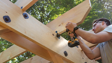
Built from locally sawn hemlock, this functional outdoor feature uses structural screws and metal connectors for fast, sturdy construction.
Highlights
"I have learned so much thanks to the searchable articles on the FHB website. I can confidently say that I expect to be a life-long subscriber." - M.K.
Fine Homebuilding Magazine
- Home Group
- Antique Trader
- Arts & Crafts Homes
- Bank Note Reporter
- Cabin Life
- Cuisine at Home
- Fine Gardening
- Fine Woodworking
- Green Building Advisor
- Garden Gate
- Horticulture
- Keep Craft Alive
- Log Home Living
- Military Trader/Vehicles
- Numismatic News
- Numismaster
- Old Cars Weekly
- Old House Journal
- Period Homes
- Popular Woodworking
- Script
- ShopNotes
- Sports Collectors Digest
- Threads
- Timber Home Living
- Traditional Building
- Woodsmith
- World Coin News
- Writer's Digest


Replies
Yur in it ... Ask away.
Just remember information on the problem is a must...
Who ever invented work didn't know how to fish....
Well, as long as you offerred........1968 tract home, Colorado, originally a 3 bedroom ranch, had 2nd floor added plus new service. Old box in garage used to feed original part of house by running cable from new service. Construction required some original wiring be moved or rerouted. One original bedroom has no power. Owners ran short of cash when man of house disabled. How best to determine how house was wired (sometimes if a breaker is shut off say for the LR an outlet in adjoining room goes off too) Is there a normal method of wiring a stick frame house and how can a test the existing, in wall, wiring to make sure a new run ties in only with the unpowered lines in the BR. Now if a circuit came from the box to the ceiling j-box in that BR and a switch leg was run and a few wall outlets that would be just too easy! Any ideas? Tyr
Man are you in luck. There's a couple of posters that live in your nieghborhood. Intisement may be the order of the day.
Tried to break this up to be a little more understandable...
That BR receptical on the LR circut isn't a big deal. Mark the breaker accordingly.
How best to determine how house was wired (sometimes if a breaker is shut off say for the LR an outlet in adjoining room goes off too)
Rip open the walls... LOL.. Turn off a breaker and test every thing you can get to. Mark said breaker accordingly. Don't forget to turn it back on.
One original bedroom has no power.
Look into your recepticals to see if you are short a make up(connection) or have an open for that room.
Is there a normal method of wiring a stick frame house
Sorry to sound like a SA but define normal. Do you see something you believe to unordinary or out of line?
how can a test the existing, in wall, wiring to make sure a new run ties in only with the unpowered lines in the BR.
Test everything you can get to to see if it is hot. You may only have a bad connection in one of the recepticals or do think you are missing a feed?
Now if a circuit came from the box to the ceiling j-box in that BR and a switch leg was run and a few wall outlets
Recepts and lighting is / are seperate circuts / breakers.
Are the walls open? (no drywall)
Who ever invented work didn't know how to fish....
No walls all rocked--house built in 1968 and lived in ever since--even through the addition. I'm a hands one GC and this seemed to be a problem I could solve--but I didn't want power to existing BR to come from two sources so I figured a new run from the original breaker would do it. But where to connect? Thus the ? about a standard (dream on) way a room would be wired. The remodeler no longer remembers what he did except some wires in the old attic were in the way and had to be rerouted.
Find out where / what every breaker powers and services.
You may find a left over breaker doing nothing. Trace that feeder and see it goes to the problem child. Check for a faulty breaker.
Hunch says you have an open early in the circut. Be it hot or a neutral. You could rig a wire to a working neutral and meter the hot side and see if the hot side is active.
You can ohmn (continuity check) this out with the power turned off.
Who ever invented work didn't know how to fish....
Open up every box in the room and find from/to for each one of the cables. The one that you can find the other end of is the old feed cable.
There are a few circuit-finder tools that may help you. Some fairly cheap, like $20. You plug a gizmo into an outlet, then run the detector gizmo over the breakers in the panel. It lights up when you found the right breaker. Usually. That will help you to map what circuit is connected to which breaker. There are also sniffers that you can use with a tone generator. Those will let you trace a wire inside a wall, but they're expensive.
There's no standard way to wire a house. I've seen some that had 4 fuses that run the whole house and some with a nicely labeled breaker for every room. More modern homes have tighter requirements, like dedicated kitchen, bath, refrigerator, etc. circuits. Older homes can be any which way. Several rooms on a breaker is common, particularly when they are adjoining rooms. You'll have to do some leg work to map out what circuits run where. A helper and walkie talkies are handy. One at the panel and one in the house. Keep flipping breakers until you know which one runs every light and outlet.
Will these circut detectors work when the outlet in question is not working.. I suspect not.. because there may be a bad connection somewhere along the line.. ie. if a few outlets in a run stopped working.. how would you begin to determine a- what circut they belong to, b-what what is upstream of that outlet? is there a "where the heck does this wire go" kind of detector?
Any ideas?
"is there a "where the heck does this wire go" kind of detector?"
There are remote 'circuit tracer' devices made for this very purpose.
One source: http://www.professionalequipment.com/xq/ASP/id.5/subID.269/qx/default.htm
One low budget method is to use a standard voltmeter with a continuity setting, and run a long jumper wire or extension cord to the other end. Just make sure the power is off!
There are good circuit tracers available that work on unpowered wires. You'll need to cut all the breakers off. They don't work on powered wires, or at least mine will not. You don't want a signal feeding through a breaker into another circuit. You also might need to unplug about everything in the house. Not cheap items. Mine was a couple or 5 hundred. You may be able to rent one? They are handy.
"One original bedroom has no power."
Check for a tripped GFI receptacle. If the bedroom's on the same circuit,,, no power
Thanks, but this house was fully built in 1968--probably long before GFI's were even invented.
> Is there a normal method of wiring a stick frame house ....
No, but there's usually some sort of logic to it. Get a sharpie and some masking tape, and start early on a nice bright Saturday turning off all your breakers but one at a time. Number the breakers, and go around checking and numbering the plugs and lights to determine exactly what's connected to what.
Turn all the power back on, and draw a floor plan with the numbers transferred to it. Study this drawing a while and some of the logic may become clear to you. You might be able to see how lines run from the panel to the various loads. You may find one circuit with very little on it that seems to die off going in the general direction of your dead plugs. If so, the last of the live and first of the dead boxes are good places to start looking for the problem. Also be alert to the possibility of hidden boxes. Sometimes people plaster over them and such.
Keep the drawing at your breaker panel for future reference.
-- J.S.
I'm a hands on GC, so not my house. Almost all rooms have their own runs to a breaker controlling just one room. The BR in question had its original circuit changed about 1982 during a remodel. Remodeler no longer around. Owner tired of running an extension cord to the one BR. I just figured I could start at the original breaker and run a new line to the BR but how to connect it without having two electrical sources feeding a single line troubled me. Not much room to manuver in remainder of attic--especially to outside walls
Open everything you have not working. You may have a faulty connection at the brginning of the circut. Maybe a broken wire inside of what apears to be a sound connection.
If you power up the bedroom make sure all the other breakers are off when you turn on the power. Meter all the wires hooked to breakers. Look for a back feed from the bedroom.
Turn the new breaker off and turn on all the others. Check for back feed on the bedroom feeder.
You will also have to make sure you haven't any loose hot wires in the walls or crossovers in the lights and recepticles.
Who ever invented work didn't know how to fish....
"You may fire at will, Gridley"
There are several qualified electricians who frequent this forum.
Try to explain any issues in detail. Include any results from testing or any attempts at correcting the problem. Knowing your geographical area might help narrow down the problem, this time of year AC loads don't pose too much of a burden in Northern Alaska, and give a clue as to what rules might apply. The better the information the more likely a good answer will be found. Don't worry about getting the technical terminology correct.
Pretty good group of folks here so you will have a lot of people trying to help and pulling for you. So don't be shy.
I recently installed a new bathroom exhaust fan in an older house where there previously was none. I tapped into the circuit that controls the existing light. When I turned the switch on, the fan ran and the light worked but was very dim. I thought there might be a defect in the fan, so I installed another. Same problem.
Some specifics: Switch is at the end of the circuit. 2 wire rag rap, no ground. Fan is between switch and light. Spliced in a piece of wire in order to locate the fan in the center of the ceiling. New wire is 14g. Old wire probably 12g. Fan wired to the hot side.
Any ideas?
Very possible you wired the fan and light in series and not parrallel. The fan motor is hogging all the jucie and starving the light.
Who ever invented work didn't know how to fish....
Remember, the switch is at the end of the circuit. Fan and light are between the line feed and the switch. Wiring the fan and light in parallel means both will be constantly on. Any suggestions?
Wiring the fan and light in parallel means both will be constantly on.
Wired correctly the fan and light will be on at the same time when the switch is on. Both will be off when the switch is off.
Gang (connect) your whites from the light, fan and neutral from the power feed together.
Gang the black leads from the light, fan and the POWER LEAD (hot wire) from the switch. Make sure you confirm which wire is the hot FROM the switch. The possibility exsists that it could be a white wire. If it is a white mark it with colored tape or paint it with a permanent felt tip marker. Red would be a good color for this. Identifying it different from the other wires is a good idea anyways even if it's black. Cuts down on mistakes and makes life easier.
Don't forget to make up all your grounds.
This is important... Are there any wires left over?
MAKE SURE YOU CONFIRM WHICH WIRE IS WHICH and where it is coming from before you start making conections.
Who ever invented work didn't know how to fish....
This is important... Are there any wires left over?
If I understand you correctly that would leave the hot from the power feed and the neutral from the switch unconnected.
Where does the power feed 1st come in?
Switch or cieling box?
Who ever invented work didn't know how to fish....
Light fixture
Black feeder (hot) to black wire going to the switch. White wire from the switch (now colored red) to the black light wire and black fan wire.
White feeder (neutral) to the white wires on the light and fan.
A nagging thought... (caution flag) You mentioned the neutral from the switch. Is this you thinking the white wire is a neutral as where it really could be a hot only not marked accordingly.
Who ever invented work didn't know how to fish....
Okay. I get the wiring. Sounds right.
A nagging thought... (caution flag) You mentioned the neutral from the switch. Is this you thinking the white wire is a neutral as where it really could be a hot only not marked accordingly.
Yes, I was calling the white wire from the switch the neutral. There is only one line coming into the switch box with a black and white wire. If I'm wrong, how would I test it?
You have an ohmn meter.
The switch in the on posistion. You get a reading across the white and black wires. Switch off. No reading.
Open the switch box and do a visual.
Who ever invented work didn't know how to fish....
Has this job killed you yet or least welded your jewels to the real estate?
This amount of time between posts... Yur startin' to worry me...
Who ever invented work didn't know how to fish....
Nope. Just took a break.
You done yet???
i'm waiting for my beer...
Who ever invented work didn't know how to fish....
Thanks, I got it all corrected. Had to install another wire to get the parrallel circuit, which is what I was trying to avoid. Regardless, I owe you a beer so take this message to any bar in America ( I've been to every one and they all know me. ) and collect your cheer.
To whom it may concern:
Give IMERC a beer and put it on my tab.
Gridley
( OH GREAT ONE )
Had to install another wire to get the parrallel circuit
You sure know how to make somebody cringe. Which wire is that?
PS Can't drink, allergic to the stuff. You're off the hook.
Who ever invented work didn't know how to fish....
I'd have to diagram it for you and don't know how on this forum. Besides, it might make me look stupid when you figured out a better way.
Does it work?
Is it safe?
Is it leagle?
Who ever invented work didn't know how to fish....
YUP!
yup!
YUP!
Okay....
Let's do coffee instead...
Who ever invented work didn't know how to fish....
You got it. Thanks for the help.
Most of the confusion about the circuit was because I forgot to mention that the light and the fan are 3 feet apart. Wiring it as per your instructions still puts it in series, so I had to add a line to make it parrallel.
Wiring it as per your instructions still puts it in series, so I had to add a line to make it parrallel.
Now ya done it...
The way I said to wire was not in series. Something was missed in the translation.
Who ever invented work didn't know how to fish....
Try this...
Can't post an attachment for some reason....
Who ever invented work didn't know how to fish....
Don't overlook my question from last night: what size breaker feeds this circuit ?
Not sure. Will check, but when I wire them in parrallel they both work just fine so they are not exceeding the amperage.
Your statement is incorrect. If you wired 50 100 watt light bulbs in parallel, they would all work just fine up to the point the circuit breaker tripped or the insulation melted off the wire feeding that circuit.
But that's not my point at the moment. Your original description of the problem said you added 14 AWG to a circuit that was, probably, 12 AWG. If this is on a 20 amp breaker, you've violated all known codes and created an unsafe situation. It's troubling that you didn't check the breaker size before adding smaller wire than was already there.
IMERC is right on - It sounds like you have the fan and light wired in series.
To find out if this is the case, turn the switch on, then unscrew the light bulb. If that kills the fan they're wired wrong.Why don't you ever see the headline "Psychic Wins Lottery"?
I just did the same kind of project. You need to have two splices in the knob and tube, one in the hot wire and one on the neutral. You will have two wires going to the fan, one for the hot and one for the neutral. I used four boxes to house all of the wiring, as once you cut into the knob and tube, you won't have enough slack to put all of the wires in one box.
Aaron,
What area of the country are you in?
Indianapolis.
What size circuit breaker is this wiring on ?