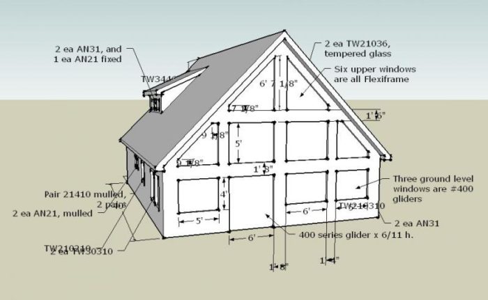
Step us through how you would frame this. Two pics are attached, one of the little house, with its windowed gable end showing, and our idea of framing.
The wall is 30 wide x 25 tall at the peak, and there is a cluster of 4 2x6s at center that are picking up the structural ridge (a 2-ply LVL 18.)
We’ve no telescopic forklift available, but can get cranes in various sizes.
The windows have no headers because there is no load.


Replies
I can't help on the framing but I like the look of the shed dormer much better than the gabled one.
Tom
Douglasville, GA
Actually therre is quite a load - a wind load on that wall.
I might even consult an engineer, but to start with - I woiuld double the horizontal plates in the box headers between windows and would add blocking continuing that line to connect to the built up timber in center un=der the ride beam.
I might use steel strappiung toi tie some of those connections continuous ly on both sides too.
Welcome to the
Taunton University of Knowledge FHB Campus at Breaktime.
where ...
Excellence is its own reward!
I agree with the possible wind load, this summer had to go and fix a wall like that one. The amish had framed it with precut 2x6's and it moved when you leaned against it.
The GC had to have ironworkers come in and reinforce the wall with a 3x10 tube steel frame in between the windows from floor to the trusses. The steel frame was 36' tall. And quite expensive.
I got the call to fur out the walls with 250 8' 2x12's so the wall could be plastered. It was a royal pain and alot of work handling 2x12's three to four stories in the air.
Gene do yourself a huge favor and get an engineer to put a stamp on this thing. My personal experience is just a small reason. Because the stamp I got was not an easy one or cheap for that fact. Much harder the second time around.I only golf on days that end with a "Y".
Pif, you are preaching to the choir re the wind load. And shear is a concern, too.
I wonder how many of these "vacation cabins" get built. The plans websites, from which my client got his idea, show plenty of these houses with tall gable ends shot through with big windows.
I had these thoughts, so let me try them out on you.
Each of those "spandrel headers," the 4 lowers at 5' and 6' widths, and the uppers at 6', would be made with a 2x6 perimeter frame, and the "studs" would be ripped to 4-1/4", with an "inlay" panel made from LSL rimboard at 1-1/4" thickness.
The two large "columns" between edge windows and inside windows have a 10" space between the homerun 2x6 studs, and these spaces would contain LSL "webs" flush to the outside studline, with everything well glued and screwed.
The center cluster, with the 4-pack column, and the flanking homeruns and jacks, has two 4" spaces, and we will inlay rips of rimboard there, all glued and screwed.
We'll sheathe with 3/4 CDX on the outside, and after running wiring and doing our spray-in unsulation, we'll sheathe inside with 1/2" CDX. The two side bays will have 2x6 crossribs spaced at 24"
We will be certain to sheathe each cruciform connection with a full sheet, so the sheathing joints all meet halfway between corners, up and down. Blocks will be at joints.
This is probably overkill, compared to how most of these get built.
see an engineer. Too complicate for me to assure you
Welcome to the Taunton University of Knowledge FHB Campus at Breaktime. where ... Excellence is its own reward!
Gene,
Why would you need a crane or a forklift for that wall?
Why would you need a crane or a forklift for that wall?
Observations and question of a true framer.
Build a scaffold and frame it in place. The scaffold would then be used to set the windows, install corncie and paint.
blue's plan of continious vertical members and the red horizontal member seems adequate to me / I think I would use 2 x 6s wall framing and solid sheath with plywood / cutting out window openings with a router after sheathing / sheathing should break at mid header locations effectively reinforcing the header / stud joints
Call me stupid but it worked in the home attached to the followong post
Signed, Retired Framer
Edited 6/7/2006 12:53 pm ET by txlandlord
Maybe this wall is similar, maybe not, but it gives me an opportunity to show off.
Pics of this project have been posted before. the overall project is much more than the home, including a $45,000.00 kids play house, a 70' brdige over a lake with a 16" octagonal gazebo in th center, an 30' observation tower / dive platform, 1200 SF shop with apartment above and a $22,000.00 garden / potting shed. All 1992 pricing.
We framed and built this home when we were doing "in house" framing as a part of our custom home building business. Circa 1992.
The porch helps the wall, but the wall was framed with continious vertical members and was substantial before the applicaton of the porch. The outside view of the gable wall seen in the exterior frame shot is on the left in the interior finish picture. Note the flying beam in the 30' x 64' Great room stabilizing the referenced wall.
This house was a blast to build.
The fireplace mantle (not seen) was a piece of pecan 9" thick / 30" wide / 9' long. It is substantially secured without corbels or additional support within the wall and appears to be floating. The HO questioned its structural integrity, at which time I instructed trhee of my empoyees to stand on it and jump up and down.
The Great Room wall are covered with rough sawn 10" western red lap & gap cedar with the reverse side smooth v-groove pattern used on the ceiling. The beams and columns were covered in red aromatic cedar. We got the HVAC system up and running during the interior finish work and stacked all of the cedar to be used in the home for three weeks before application.
The home is 11,400 SF total with 6800 SF of living area, including the aforementioned 30' x 64' Great Room. Gable end walls were 16' and rose to 32' at the peak.
We applied a standing seam metal roof with the main panels being 42' long. The outside facia and beam trim is rough sawn western red cedar full 2" material and Austin white limestone. The stone mason worked on the project from November thru March.
The project was completed in 18 months for $1,200,000.00 in 1992. Interior cabinets and trim as I recall was $130,000.00 and included an 8' gun rack hidden behind a set of hinged bookcases. The HO was so proud of the hidden gun rack that he showed everybody. I told him he was screwing up as the secret was no longer a secret.
Not to offend anyone, but for a 1.2 million dollar place it looks very very boring. And kind of dark. Perhaps that is just the photo or perhpas the porch blocks alot of light.
No offense taken.
Probably the darkness is due my own photo skills in 1992 or maybe just a cloudy day, becasue it is plenty bright.
I do agree with you, as we built from the architects plans we made frequent comments about what could have been done with 1.2 M.
To further explain, the home is Texas Hill Country style, with all sorts of accents like Texas Stars in the wrought iron and a State of Texas stone in the fireplace. It is rustic and somewhat plain, but built to order, with lots of gizmos and gadgets.
txland, do you know if it was designed by an arche?
txland, do you know if it was designed by an arche?
Yes, the home was designed by an architect. He was really up on energy efficiency methods. The home had amazing performance. The client rented a 1400 SF 3 bedroom farm house that is on my property while the home was under construction. After moving into the new home he told me his utilities bills were less in the monster house than the old farm house.
The architects name was Batho. In the design stages there were so many changes we ended up with 100s of 24' x 36" drawings that were old designs. I told the client that he could paste the old plans in a random collage above a Texas style wainscote in the bath room and call it the "Batho" Room.
I'm thinking along the same lines as Piffin. Those tall skinny sections of wall will have to be cobbled together to form enough shear wall for your local wind and seismic conditions. Also, wind loads directly into the wall can be serious if you're in a high wind area.
The size and shape of it reminds me of a great room on a high ridgetop summer home in Wyoming. The wind was comming directly at the wall and during a 50 mph breeze the wall would move in close to 3/8". At 75 mph with gusts going quite a bit higher it was simply scary.
Sheathing both sides of the wall will increase both shear and direct wind loading by a considerable amount.
Depending on your interior layout, sheathing some key interior walls can also be a wise choice in high-wind areas.
If it were my personal house and there weren't local building inspections requiring an engineer's design (most of Wyoming), I'd spend the $500-700 that a structural engineer would cost and invest it in plywood for interior sheathing and Simpson shear anchors. However, when building for clients the engineer's opinion will CYA.
Cheers,
Good question Gene.
I suspect that I'd frame this different than most people. I'm curios to see your results.
For me, the most important thing to do is to stabilize the gable end from shaking in the wind. I try to stiffen it as much as possible by looking to create doubled and tripled framing members. Conventional wisdom tells us to look at the vertical members for stiffening, but I always look hard at the horizontal opportunities too.
Heres a pic of how I'd do it. I've framed a lot of gables like this and I often include horizontal stiffening members.
The red members would be my anchors. They are strategically located to lock themselves into the roof system and the spans are short enough for me to know that they will remain quite stable under a wind load. I'd be thinking of at least a triple somewhere in that window framing. I might even triple up three 2x12's or glulams. The goal is to get some beef at that level.
The interstecting members that go into it will be manageable after that member is in place.
I've used this same theory for years in our two story foyers. Other crews use tripled 18' king studs to stabilize the kings on the doors and window in the foyers, and I've always ran my headers wall to all. This breaks up the wall nicely and the foyer beam is usually under ten feet.
Now I'll mosey onto the other ideas.
Blue,
I was pretty close to the way you called it. The only difference for me would be that red (orange) header. I'd have a doubled or tripled if I had the room king that went up to the rafter on the outsides of that header.
Sheathe that wall with 10' sheathing and block all panel edges. Around here, we'd have holddowns and possibly 3/4" sheathing for that wall (1 side) nailed off with 10d nails.
Gene,
I hope you post pics :-) and nice job with SketchUp.
Tim, I'm pleasantly surprised that we're all on the same page. Around here, I don't see too much thinking along these lines and we have a lot of tall walls like that.
I thought about what you proposed and wouldn't hesitate to do it your way too. I think it's half dozen of one, twelve of the other.
One thing I wouldn't do is raise that thing without a crane or machine. If we couldn't get our machine out back to set windows, the windows would be set while the wall was laying flat. With all the trim and overhangs, this wall would be one heavy, top heavy mutha! I could only dream of framing it with only studs like Joe does. I've raides dozens of them with wall jacks and I hope I never, ever have to do that again.
I hope Gene posts some pics too.
blue
One thing I wouldn't do is raise that thing without a crane or machine
But think of the stories lifting that without a machine would generate!! :-)
blue, your red header breaks the post used to support the ridge beam. Is that okay? It seems to me that you would like that post to be continuous, top to bottom.
I had the same thought. Blue seems to want to get braced crossways, but I think it is creating a hinge.
I like the idea of horizontal strenght, but would not think you would like to break that main post. I don't know if you could knock the post to recieve one horizontal 2 x 10 or 2 x 12 to run from one roof rafter to the other, and a) add very much additional horitontal strenght and b) not weaken the main post.
??????????
And Gene, what connectors do you use to tie the post to the ridge beam?
Gene, you will have a hinge on the horizontal member if you run the vertical one continuous.
I can pretty much tell you that a 27' member will flex to a very large degree.
I'm not taking into account seismic requirements. I have zero experience dealing with seismic issues and those values never enter my mind when I frame things.
blue
DoRight, I don't see the need to provide a continuous post. I do see the need to limit the flex and if you do a quick scale, you'd see that the continuous post would require a much longer member. The longer member would flex more.
I'm no engineer, so my way of building could be wrong. So far, I've never had a structural failure in anything I've built. I have fixed a lot of things that engineers said would work though!
blue
OK. So is the stability for the ridge beam offered solely by gravity and numerous rafter connections and the ridgitiy of the roof shealthing? Is that how that works?
One of the issues raised is wind loading. So if the wind is pushing on the roof and the beam is more or less floating on YOUR horizontal brace, is it the roof shealthing that keeps teh whole roof from pusing over?
Gene, I have no techincal help for you, but have a question for you.
How or with what do you make the connection between the ganged 2 x6 post and the ridge beam?
Do you have any flooring behind those Headers? Tie 'em together.
There is nothing behind the wall inside except space. No walls, no floors, no pilasters, just air.
Just about every website there is that is selling home plans, sells plans for houses like these. Lots of them.
Every kit house manufacturer doing biz selling vacation houses sells models like this. Lots more of them.
Some must get built, and I cannot understand why others have not chimed in here with suggestions from experience.
I have thought about framing the whole thing pretty much as my CAD sketch shows in the earlier post, but using 2x8 throughout, and chopping horizontal slots into the verticals at each spandrel line so that 2x2x1/4 steel angles could be bolted on, thus tying the whole thing together.
But I have a feeling that I am over-thinking the whole thing.
Simpson Strong Walls for the verts.
Full length Ladder Joists, boxed with 3/4" both sides, glued and nailed to seismic schedule as full width headers. Center the ply (ran horiz) on the +'s. Strap the ridge column across the headers.
Get the Electrician there before you box the interior.
For a garunteed, no-fail, rigid-as-stone effect, add an interior 16" or 32" "balcony" of a boxed ladder joist to the upper header. Tell 'em it's to make window cleaning easier and a place to hang plants from.SamT
2x2x1/4 steel angles
I have helped frame such a wall and the boss (former engineer) wanted some angle let into the frame. What it did do was weaken everything that it crossed to the point that the benefits were nill. After the fact he agreed that it was a bad idea.
:-)
some here have worried about the wall flexing. If so screwing or bolting angle iron to a couple of the verticle memebers could work and would not "cut" any other member (as trout mentioned).
??
trout, I agree.
A 27' long piece of 2 x 2 x 1/4" would flex about as much as a 2 x 4.
I've done a lot of these things. The trick is to make the core stiffeners as short as possible.
If I were forced to frame this with 27" member as my anchor, I'd insist on 2x 10 or 2x 12 walls. I've retorfitted a few of these that were built to the architects specs and didn't work.
blue