Another Bearing Ridge Question
Tomrocks21212
| Posted in Construction Techniques on
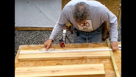
While I was out scouting for work last week (something had better turn up soon), I visited a site that was about 95% framed. The great room had a huge multi-lam bearing ridge, 2x rafters spanning maybe 15 feet from plate to ridge, but….
I’ve never seen one where the rafters are tied to the beam with plumb-cut, nailed connections. The few that I’ve worked on, we always put a birdsmouth cut at the top, so the rafter would rest ON it, not against it.
Is this builder introducing a horizontal thrust to the rafters? No TECOs or other fasteners were in evidence, just about 7-8 toenails.
I guess as long as the nails hold it’ll be okay, but it made me wonder about the longevity of such a roof.
Comments?


Replies
Around here on LI thats pretty much how it's done "most" of the time.
The birdsmouth is just cut to the plates....and it ya really wanna get freaked out you should see how the ridge is done on my house....The rafters at the peak butt one another with no ridge beam....'course my house is 326 years old...lol
http://www.cliffordrenovations.com
http://www.ramdass.org
Edited 4/7/2009 6:24 pm ET by andybuildz
I understand the no ridge detail. It doesn't really add anything to the roof structurally, it's mostly for convenient nailing. Gravity forces the tops of the rafters together.This was different. As a bearing ridge, its job is to eliminate the horizontal thrust load on the walls.
The only way for the vertical load to change to horizontal thrust is if the rafts slide down the ridge or for the ridge to sag. So the Q is whether the toenails are sufficient fastening to prevent that. On a larger span I would expect to see some hangers there too, in addition to the toenails.
Welcome to the Taunton University of Knowledge FHB Campus at Breaktime. where ... Excellence is its own reward!
That is typical for me - along with a metal strap across the top of the rafters and over the ridge to tie the three together.
Welcome to the
Taunton University of Knowledge FHB Campus at Breaktime.
where ...
Excellence is its own reward!
Does Simpson make an approved strap or do you use something else?A Great Place for Information, Comraderie, and a Sucker Punch.
Remodeling Contractor just outside the Glass City.
http://www.quittintime.com/
they do have a specialty one, but I have had a roll of strap material from them that I cut
Welcome to the Taunton University of Knowledge FHB Campus at Breaktime. where ... Excellence is its own reward!
Piff,I've framed the same situation with and without simpson hangers for a long time now, but I have never used the over-the-top strapping method. Recently I framed a roof and the strapping idea popped in my head (only because the LVL ridge had been left out and was cupped)....but then I thought about it for awhile and couldn't figure out where I would be gaining. So, why put strapping over top?When roof systems fail, they usually begin to spread at the bottom of the plumb cut, not the top. I could see running strapping from rafter to rafter under the ridge beam.BTW: all sloped roofs have horizontal forces acting on them at all times, and contrary to "rafters sliding down" which I have never seen, usually the ridge sags and pushes the walls out (very common) or the rafters deflect and pull the walls in (rare). All of these are usually remedied by properly sizing the ridge, properly spacing collar ties, using ceiling joists and possibly adding webs, and sometimes by adding metal to the system.DC
Edited 4/8/2009 8:39 am ET by Dreamcatcher
The main thing the strap over does is the same function as a collar tie in that it prevents the roof from hinging open at rige in high wind uplift.But where you are concerned the walls could spread apart from the horizontal thrust and you know the ridge beam is engineered to handle the loads, the connection of rafter to ridge is the weak link in the system.By strapping over, the rafters are tied together to counteract those opposing forces on opposite walls
Welcome to the Taunton University of Knowledge FHB Campus at Breaktime. where ... Excellence is its own reward!
That's a lot of wind!I've never seen it used in michigan though, and I still don't see the point.Collar ties, to me, help keep the bottom of the rafter from pulling away.Simpson does offer a "ridge rafter connector" that does similar to what you are doing.Do you use hurricane clips or are you strapping there too?Have you ever spoken to an engineer about strapping over the top?I guess if it works for you then it works though...even if it's only job is just to make you feel warm inside ;-)DC
Collar ties, in the upper third of the rafter span, do nothing (well, almost nothing) to counter thrust. They are intended to keep the ridge from coming apart and to provide a nailing surface for the ceiling.
Rafter ties, in the bottom third of the rafter span, do counteract thrust.
Our engineer spec's strap ties over the top for tricky connections. The straps would be wrapped under the rafters in this case.
first time I learned that detail it was from an engineeer.You are confusing rafter ties with collar ties which is common enough mistake.A coloat tie by definition is in the upper third of the rafter space and is for the purpose I mentioned, but does nothing or very little to prevent spread. A rafter tie is what is at the base of rafters and prevents wall spread, in which case no structural ridge is needed.engineering calcs do only consider vertical load at that joint to ridge. horizontal thrust only comes into play if the joints fail.
Welcome to the Taunton University of Knowledge FHB Campus at Breaktime. where ... Excellence is its own reward!
Good thought. If there was strapping, I wouldn't have seen it, but all the other framing they did looked very good, obviously conscientious workmanship. So I'll assume they put something in.
Tom,I almost forgot to tell you that here in MI, the only times I have seen the rafters sit on top of the ridge (with or without a birdsmouth) is when the ridge beam is something special like a glu-lam or heavy cedar beam that the HO wants to keep exposed. Otherwise, by placing the rafters on top, you would loose the inside peak of a cathedral. DC
This beam was huge. I'm thinking maybe 10" w x 12 or 14 tall, as I recall it was 3 or 4 MLs plus 2x on each side. A lot of it was below the ceiling peak.
Hmm, what do you think the span was?I just framed a 16' long 6:12 cathedral that only required a 14" LVL ridge. But I framed a 5:12 hip cathedral awhile ago that spanned 26' and required a double 16" LVL and 12" LVL hips.I guess 12" and 14" tall isn't weird at all but 10" wide is quite strange. Seems like a waste of money as they should have just been able to increase the depth of the beam and nail fewer together or use a Para-lam type beam or steel. It sounds like they didn't want to show any ridge inside but they needed a lot of strength. I can't say I would agree with the engineering without seeing it first hand. How did they connect the laminations? It's still less efficient than just using a deeper beam.DC
I can't really say what the actual dimensions were. I was on site for an hour, and spent maybe 2 minutes in this particular room, and I was talking with the site super the whole time.
I didn't have an issue with the size of the beam, I just thought the upper connections looked kinda sketchy.
But the idea that maybe there were straps holding the rafters together that I couldn't see makes complete sense.
So I'm a little smarter now than I was yesterday, and that's a good thing.
The force on the rafters is exactly the same as it would be if it were a flat roof with a beam at mid-span. Would you be comfortable attaching the rafters to the beam using nails and no hangers in that situation?
"The force on the rafters is exactly the same as it would be if it were a flat roof with a beam at mid-span. Would you be comfortable attaching the rafters to the beam using nails and no hangers in that situation?"I'm no engineer, but I've learned enough about physics and structural loading to know that's not at all true.Any object with an angle greater than zero has a horizontal component. The greater the angle up to 90 deg, the greater the horizontal component's ratio to the vertical component. Think about when you build the roof and you can sometimes get the rafter to stay put before any nails are in it, that is just an equalization of acting forces helped by some friction. All rafters have at least two force components, beams usually only have one. A flat roof (hypothetically zero degrees) has only vertical force. Therefore: Apples vs. OrangesDC
Close. As the angle approaches 90 the horizontal forces are reduced.
If the rafter is constrained at top and bottom, then the forces are calculated just like a floor beam.
"...If the rafter is constrained at top and bottom, then the forces are calculated just like a floor beam"which doesn't happen too often in residential construction.Not too often that I've hung rafters between two concrete abutments :-)Thanks for the clarification...gotta learn as I go here!DC
If rafters weren't constrained at the top and bottom, I don't know how they would stand up. If a rafter is properly attached at the bottom (birdsmouth to top plate the most common) and is suppported by a properly sized ridge beam, then it can't move up, down, in or out. IF it moves, it's not constrained.
For a rafter to drop, the ridge has to sag. If the load on the rafters tries to push the ridge sideways, it will have to stretch the rafter in length. Unless the ridge drops. Which it can't if it's properly sized.
Oh, and when building in hurricane-prone areas, you need to do one of two things. You can use impact-resistant glass on all the doors and windows so windblown debris can't break one and let in a sudden gust of wind--which would blow the roof open at the top like a christmas present. Or, you can use enough metal connectors, such as hurricane clips at the bottom and straps or hangers at the top of the rafters.
I don't think he understood what constrained means.This while issue is one of those things that is simple once you grasp it, but can easily be misunderstood when there are preconceptions about what IS stuck in a person's mind, so there is a mental barrier to jump over first - paradigm shift kind of thing, where the light comes on.
Welcome to the Taunton University of Knowledge FHB Campus at Breaktime. where ... Excellence is its own reward!
I think this proves a few things outside of this particular topic that I have adamant feelings about. 1.) carpenters should have a proper education in the physics, trig, and calculus of structural forces. and 2.) engineers and architects should have active, first hand knowledge of what actually goes on at a construction site. Then both would know the truth of what is and is not happening in application.As one who has actually had both experiences, I can say for sure that nothing in home construction is ever perfectly constrained...everything moves. Wood ALWAYS deflects. Even properly sized beams deflect both vertically and horizontally. And while it's usually a small, elastic, and tolerable amount, the fact is that it's still there. That is your undebatable fact. I don't believe I said anything about "thrust" which is simply the resultant of the component forces, but since there are always forces acting concurrently on any inclined surface, then there must be some thrust resultant, however slight. This is wood construction we are talking about here, components are not welded into one comprehensive piece and therefore it doesn't matter how many nails, screws, bolts, or glue you throw at it, it's all gonna move independently.Also considering constrained points, it's more or less just theoretical since the points and methods of constraint are imperfect in application and do tend to move over time. Open any old roof and wiggle the rafters that are simply toenailed in to figure that out. Wood swells, shrinks, twists, cracks and splits, nails bend and corrode and the whole system develops more and more play. That's where the theory falls short and actual application proves fact.Do mechanical connections help, yes. I am not debating that. Do roof systems fail, yes-often, but rarely catastrophically. Don't get me wrong there.Now, I get the feeling I am not here telling you guys anything you don't already know; and trust me you haven't given me any new insights either. Perhaps we just have a difference of terms, experience, or opinion but there can be no difference in fact; such being that there are horizontal forces acting on every rafter regardless of cut, shape, or angle between zero and 90 degrees inclination.The strap over the top thing....maybe it's regional, maybe it's just a safety blanket. Doesn't matter really, I just asked who's idea it was and wanted some better explanation why. If the reason is because windows blow in and allows in wind, that's fine with me and a plenty reasonable explanation; maybe rare but reasonable and understandable.I may be speaking somewhat technical here but I am also speaking from a realistic standpoint of having seen the actual results of good and bad engineering in actual structures. I have calculated them, put them together myself, and taken them apart. That should count plenty.Now, to act as if you think I am some sort of moron who cannot wrap my head around what you guys are saying is just rude. You are not stating any new or revolutionary theories of structural physics, it's plenty old and widely available information that I am well enough versed in and quite proud to be...i've been taught, learned, and been tested just as many of you have.So, does this really need to continue? Is toenailing a rafter to a ridge good general practice? yes......and that is the only necessary answer. case closed.DC
I don't intend to be rude and I know very well from your posts on other topics that you are a knowledgeable builder, but in this discussion you persist in stating facts that are just plain wrong.
There are no horizontal forces acting on the rafters no matter how much you seem to wish there were. However you came by that belief, it can't have been from an engineer or engineering texts, and persisting in a belief when confronted by contrary facts is no way to conduct an argument.
So toenailing a rafter to the ridge is not necessarily good practice, and the case is not closed.
There are no horizontal forces acting on the rafters no matter how much you seem to wish there were.
It really depends. In the ideal case, you're correct. But... I think this is his overall consideration:
If those toenails are allowing that connection to slip down a bit, then, there is absolutely horizontal force.
The orientation of the plumb cut does matter. If the cut were horizontal and bearing on the ridge directly, or on a hanger, then that horizontal surface of the member is the bearing point.
If the cut is plumb, then all the vertical shear load at that point is being carried by the nails, not the member.
Toenails could theoretically support that kind of shear load, if they're really carefully done, and the rafters aren't spaced at their max. In the real world though?... I'd assume vertical displacement at that connection, with resulting horizontal forces.
Personally, I'd want hangers with horizontal bearing, like joist hangers. Then, there's no vertical displacement, and no resultant horizontal force. Or, angles, with tico nails (and possibly pre-drilling into the rafter end). I think that was his basic point too.
His question boils down to what the real world shear strength of a toenailed connection is.
k
"His question boils down to what the real world shear strength of a toenailed connection is."That I can agree with and why way back near the beginning here I said that with a longer span I would expect to see some hanger hardware up there
Welcome to the Taunton University of Knowledge FHB Campus at Breaktime. where ... Excellence is its own reward!
I think we're just beating our heads against the wall.
No one is blinder than he who will not see
You haven't done a thing to say where this imagined horizontal force comes from, only said that you are right and the rest of the world is wrong.The only way any small amt of the downward load is transferred to any kind of horizontal thrust is if there is a failure in the joint connecting rafter to ridge or if the ridge is in failure. But the force comes from that vertical load in the first place so the joint must be designed to resist that vertical load to begin with rather than trying to design against an imaginary load that does not yet exist.
Welcome to the Taunton University of Knowledge FHB Campus at Breaktime. where ... Excellence is its own reward!
The horizontal force is a resultant of vertical force being split into it's component forces. Let's say you have a point load such as a person standing on the middle of a 12:12 (45deg) rafter. The force does not go straight down, if it did the rafter would just shear at the point load and the man would fall. Instead the load is redistributed as the forces break into their resultant magnitudes/directions to put them back to the vertical alignment.so at this point we can see that the force must travel from the center of the rafter diagonally up 45deg and down 45deg. That diagonal force can only be rationalized if we break it into two comoponents of force, that being the vertical component and the horizontal component. The vertical component shall be the lead indicator of the shear force that will be applied to the toenails and the compressive force applied to the top plate of the wall. The Horizontal force shall indicate the compressive value on the ridge beam and shear value at the nails of the birdsmouth. Proof of this horizontal force can be seen if only one side of a roof systems rafters of a long span are placed then there would be a resultant outward bow of the ridge. An even better example of this force can be seen in the use of an extension ladder against a wall. There is no sure connection at the top or bottom, only the friction from the distributed forces (note: the frictional connection can be directly related to the limited holding power of nails and such). If the friction were to fail even slightly then the forces would result in thrust; that being vertical at the wall and horizontal at the ground. So, I hope that helps to explain it. It seems elementary to me now, but I still remember years ago when i struggled to learn it. And this is the easy stuff. It gets more complicated when you get into multiple point loads, wind and rotational forces. I remember doing calculations on giant truss systems that would take an hour or more to decipher force resultants and tensions/compressions.You really should get a book and do some reading on the subject (not being condescending here) it's very liberating to be able to calculate actual loads in construction than to have to call an engineer or over-guess. It saves time and money.DC
Hi Dreamcatcher, I'm nowhere in your league but I appreciate and agree with what you are attempting to explain in this thread. I only had a few years of engineering and architecture but remember clearly using vector diagrams to show the dispersal of forces vertically and horizontally. This concept comes up frequently and seldom do folks accept the truth you are stating. Guess that's what makes life interesting.Let's not confuse the issue with facts!
I've used the top strap before in an I joist detail. It's in the GP guide here
http://www.gp.com/build/product.aspx?pid=1390I'll try attaching a screen shot of the detail.. maybe it'll work.notice the asterisk for joist size and slope, straps only needed for large 16" joists and/or steeper slopes.The steeper slopes, sure... but why the requirement for just the 16" joist?
Edited 4/9/2009 9:14 am ET by egdc
I've followed this thread mainly out of curiousity about how the arguments back and forth have gone like spinning wheels on ice. I was trying to visualize the forces involved, and I came up with the following, which I hope will help the discussion. I think that post #43 was spot-on in analysis of the forces.Consider first a rafter that is connected to the wall plate with a hinge, then lowered so that the plumb cut rests against the face of the ridge beam (no nails or other physical attachment). Imagine also that the face of the plumb cut is well greased. In this case, at the rafter-ridge contact there will be only a horizontal force between the greased rafter-beam face contact surface, which is vertical. All the weight of the rafter will be borne by the wall plate. The moment due to gravity pulling the rafter down will be countered by the horizontal force of the beam face resisting the pressure of the rafter against it. To balance horizontal forces, the wall must resist the horizontal thrust of the rafter against it, or it will fall over.Next consider a rafter that has a ball bearing at the bottom of the bird's mouth cut and another stuck in the bottom edge at the top plumb cut. There is a smooth and greased steel plate at the top of the wall, where the lower ball bearing rests. At the top, a piece of steel plate juts out from the face of the ridge beam, and a blob of grease is placed there as well. Lower the rafter so the ball bearings rest on the two greased plates. There can be no horizontal forces, due to the grease. The weight of the rafter is borne equally at each end.As noted by others, the real connection is by nails, and there is both friction and at times measurable deflection of the ridge beam. Thus there will be at times both some horizontal force component, but mainly vertical force on the top rafter end. Given opposing rafters at any point on the ridge, I can't see the nailed connection failing unless the slope is rather low. But any deflection of the ridge, or any downward slippage of the rafter at the plumb cut, likely will come with a corresponding deflection at the wall, I would think.
Edited 4/9/2009 10:33 am ET by DickRussell
I don't think Piffin needs to do any reading on wood frame structures and for this example I know I don't. It was one of the questions on my first year engineering exam in architectural school 25 years ago and nothing has changed since.
I'm disappointed that this has gone on as long as it has without one of the engineers that post here intervening, as they did in the thread I linked to you, which you refuse to read.
This is not a question of preference, of whether you like Makita more than Dewalt, or if 1/2" ply is adequate for roof sheathing. It is a matter of acknowledged fact. For some reason it is counter-intuitive, and I would bet that among builders a good half think as you do, but that doesn't make them or you right. For the purposes of design and calculation, and in the real world of construction on site, there is no point in working under the assumption that there are horizontal loads. They don't exist.
Do you mean the horizontal loads are somewhat balanced by rafters on either side of the ridge?
He means (I think,) that as long as the vertical shear load is adequately transferred from rafter to ridge, and from rafter to top plate, there is no horizontal force.
Say you set up an infinitely strong ridge beam, and set infinitely strong rafters on only one side of it, with horizontal surfaces cut to rest on horizontal surfaces (or infinitely strong shear connectors, be they nails or angles).
Any vertical/gravity load on that rafter would not create horizontal load. There would be no bowing of rafter or wall plate. Zero horizontal load.
In the real world, it's obviously different to a greater or lesser degree, but he's correct in terms of statics if that's what he's saying.
k
"I'm disappointed that this has gone on as long as it has without one of the engineers that post here intervening, as they did in the thread I linked to you, which you refuse to read."I'm an engineer and I posted to say you were correct. Your argument didn't need any support.Maybe try imagining a pinned connection at the ridge plumb cut and a wheel at the birds mouth resting on the plate. If the ridge does not sag there is no horizontal movement of the rafter at the plate.
Very good example.
Sorry, I had forgotten you were an engineer, and I didn't know Mike Maines was one too. I'm going to bow out of this now. It has probably gone on long enough.
I don't think the arguement was about wall thrust at the bottom of the rafter... but rather the rafter to ridge connection. DC's horizontal force comes when he applies the laws of statics to break down force vectors into it's components. I think most of this argument comes from misunderstandings.
Wow, that college physics class came in handy.
Your post makes sense to me.
That was a very clear explanation of how forces in a rafter are resolved. Being able to draw and understand a free body diagram is a very useful tool. You are obviously better educated than most carpenters out there. Using the example of a ladder against a wall is a good way to visualize what's going on. Static friction handles the horizontal reactionary force at the bottom, and the mass of the house handles the horizontal reactionary force at the top.
In a very similar way, toenails and static friction hold the bottom of the rafter in place. The load at the bottom of a rafter is typically only a few hundred pounds, easily handled by toenails. At the top the horizontal force/load/reactionary force is the exact opposite. With a conventional ridge, if you were to set a rafter in the middle of the ridge span it would obviously deflect, just as if the house wall were to move the ladder would drop.
BUT, and this is the kicker. For the ridge to deflect, the rafter needs to rotate about its base. It can't do that if the ridge doesn't move vertically. Think about the ladder on the house wall. The ladder would slide down the wall if the house moved. But if the house doesn't move, there is no need to consider the horizontal forces acting on the ladder. The only engineering calculations that matter are the vertical forces. And if you have a seat cut with the rafter bearing on top of the ridge beam, there are truly no horizontal forces involved. OK, there is a small amount of deflection, but it's not enough to warrant consideration for something the size of a house.
Edited 4/9/2009 6:07 pm ET by Mike_Maines
"Using the example of a ladder against a wall is a good way to visualize what's going on. Static friction handles the horizontal reactionary force at the bottom"
One time that static friction didn't work for me. That HURT!!!
Yeah, once static friction becomes rolling friction, look out!
Maybe you should have used toenails?!
Toenails, fingernails, whatever, when that ladder starts moving, I'll use my teeth!
k
Mu sub D: Dental Friction
Hee Hee. Geek humor- definitely what this thread needs. (And Geek is a compliment, of course).
I feel bad for almost everyone involved in this thread.
OP had a good point, initially, and was correct in his modeling of the strap over the top, too. (I think you even tried to throw him a bone by saying you'd put the strap at the bottom of the ridge/rafter connection).
But, people's intelligence/education got questioned, and it kind of spiralled from there, and now OP is sort of in a corner, and saying things which aren't true, even though, again, his original point has been validated.
Can't we all get along??!!?
k
"Toenails, fingernails, whatever, when that ladder starts moving, I'll use my teeth!"
You don't trust your fingers and toes?
I feel badly about the way this thread has gone too. Too bad the tone got so chippy. I have only persisted because I don't think factual errors should be left unchallanged. This board is a record of advice and knowledge. We all have an obligation to correct significant errors.
Edited 4/9/2009 3:28 pm ET by fingersandtoes
The irony is that DC's original concern about the toenails is valid. (The other stuff, um, not so much...)
If the toenail connection slips vertically, there will be horizontal forces (due to the overall rotation of the rafter).
Pretty much everyone agrees with that, I think. Maybe we can leave it at that?
peace,
k
edited addition- Wait! six hours later, I just got the fingers and toes joke! <grin>
Edited 4/9/2009 6:09 pm ET by KFC
It's all over my head but I come here to learn and what I'm reading overall is that:
1) you all agree and just enjoy a good debate
because
2) half of you all say that forces exist
3) while the other half are saying the same forces would exist, if they weren't restricted.
So what I'm leaving the board with today is ... a headache ... thank goodness for the virtual aspect of the internet. This would've been a bear of a conversation in person ... hope y'all don't discuss work at the fests. whew.
"so at this point we can see that the force must travel from the center of the rafter diagonally up 45deg and down 45deg. That diagonal force can only be rationalized if we break it into two comoponents of force, that being the vertical component and the horizontal component. The vertical component shall be the lead indicator of the shear force that will be applied to the toenails and the compressive force applied to the top plate of the wall. The Horizontal force shall indicate the compressive value on the ridge beam and shear value at the nails of the birdsmouth.
Proof of this horizontal force can be seen if only one side of a roof systems rafters of a long span are placed then there would be a resultant outward bow of the ridge."
In terms of statics, that is not correct.
The internal forces in the member are resolved in the member, or it fails/deflects. I think it would be best to leave Young's modulus out of this...
The only way there are horizontal forces at either end is as a result of rotational forces as the beam as a whole pivots, either at the ridge or at the plate. If the connections are sufficiently strong to disallow vertical movement (with toenails, they may not be... however-)
If there is no vertical displacement at either end, there is no rotational force, and there are no resultant horizontal forces.
take a board. tie a rope through a (frictionless) hole at either end. you can hold the ropes so that they are perfectly vertical, with no horizontal tug, even if the ends of the board are not at the same height.
If the gravity/vertical load can be completely resolved with forces acting straight up, there is no horizontal force generated, regardless of the angle of the board in space.
k
edited to add: I see Mike Maines wrote pretty much the same thing as I was typing my response. I was not rehashing his info, we both were explaining the same principle at the same time.
Edited 4/9/2009 1:18 pm ET by KFC
"If there is no vertical displacement at either end, there is no rotational force, and there are no resultant horizontal forces."That is the whole crux of this disagreement. DC seems to be saying that one must assume a failure that allows that movement at either end and thus moving on to saying that one must design for horizontal force.But if one designs for the vertical load to begin with, there never is any horizontal load to contend with. there have been many attempts to explain with examples here - imagine this and imagine that - all good ones.Here is another - imagine there is no rafter there. what forces apply?
Only one - gravity - a vertical load.No we can quibble over that one, LOL since what is geographically vertical all over the earth is geometrically different when comparing the same load in America to in Europe;)
Welcome to the
Taunton University of Knowledge FHB Campus at Breaktime.
where ...
Excellence is its own reward!
Edited 4/10/2009 6:49 am ET by Piffin
"The force does not go straight down, "gravity works the same no matter where you live.The rest of what you wrote is a wound up way of saying pretty much the same thing I already did - that you have to have fialuer of the design assembly before any horizontal force is created by transferring the vertical load.But horizontal load is NOT a "component" of a vertical load.
Welcome to the Taunton University of Knowledge FHB Campus at Breaktime. where ... Excellence is its own reward!
P,I think DC misspoke when he said the horizontal load is a component of the vertical load, but I believe I know what he meant. His point is valid that there are not just vertical loads on the bearing surfaces of the rafter. I had a similar discussion with Mike Smith, Chuck S. & SamT about a year or so ago on rafters and reaction forces and I think there's a common point being overlooked. While your statement "gravity works the same no matter where you live" is true (except for very small deflections), the fact that gravity is pulling only in one direction, down, on the rafter does not mean that the rafter exerts only vertical loads on ridge & top plate.The gravitation force effectively acts at the center of mass of the rafter (half span) pulling straight down as you said. But, if you remove the support from either the top plate or the ridge, the rafter will rotate about the other support. It will not move straight down -- yeah, I know it's obvious because it is fixed at that supported end -- but it's an important observation. Okay, now consider a rafter supported (nailed or hinged) to a rigid (structural) ridge beam, but with no birds-mouth cutout at the top plate. Lift that rafter up just enough to balance something that's barely stable, say a 1/2" dowel a few inches long, on end on top of the top plate under the rafter. Then set the rafter down on top of the dowel. If the roof has any slope at all, say 6 in 12, then the dowel will tip over. However, if you set that dowel so that it's perpendicular to the edge of the rafter & rests against the outside corner of the top plate, it will support the rafter. That is the direction of the force that the rafter exerts on the top plate & it is not vertical. The only time it would be purely vertical is in the case of a totally flat roof.In engineering mechanics the force that the dowel would be exerting on rafter would be called a normal force because it is perpendicular to the face of the rafter. It can be resolved into a vertical & a horizontal component. That, I believe, is the force DC meant to refer to in his previous post.For the rafter to stay in place, both the ridge beam and wall/top plate have to exert both horizontal & vertical forces on it, or, in engineering terms, create equal and opposite moments.I should add, I guess, that in the case of the structural ridge those horizontal forces are small -- after all, minimizing the thrust loads on the wall is one of the reasons for using a structural ridge.
Edited 4/10/2009 9:05 am ET by bd
Your assumption of no seat cut completely changes the dynamics of the situation, so it's not relavant to this arguement. I think someone else said we've all more or less agreed on the correct answer. It's time to leave it alone.
When I started in show business, I played one club that was so far out, my act was reviewed in Field and Stream [Rodney Dangerfield]
Boss,Not trying to stir up the pot at all. I was just trying to clarify a point that seemed to be misconstrued in one of the later posts. But, seat cut, or not, the net forces are the same. Assuming without just made the analogy easier to understand, I thought.As long as everybody else is happy, I be happy.
in a way we are all saying the same thing but some taking the point that you design for a static load while others viewing a need to consider the dynamic load after movement( deflection) begins
Welcome to the Taunton University of Knowledge FHB Campus at Breaktime. where ... Excellence is its own reward!
Dreamcatcher,
Good explanation in post 46. I had courses in Physics and Statics in college and I agree with you.
Edited 4/9/2009 10:10 pm ET by Doobz26
That is a common mis-apprehention about pitched roof structures, and is fairly important to understand because it should influence how the rafters are attached once a ridge becomes loadbearing. There was a very good discussion about this with a lot of the BT engineers some time ago, but I can't find it on the advanced search.
Once there is a load bearing ridge, there is no horizontal load. The reason that the rafter would slide off is because of the angle of it's bearing point, not it's own angle. If you give it a horizontal bearing point by making a birdsmouth at the bottom and cut a wedge out of the top so it was level you would see there is no horizontal force to be dealt with.
Another way look at it would be: Suppose you laid the rafter on a wall at it's mid-span so that it balanced there. Then cut a birdsmouth as steep as you want - say 12 and 12 - at the mid-point and sat it on the wall. The joist would happily stay there without being nailed, because it only applies vertical loading whatever the angle.
The horizontal load in pitched roofs comes about when the opposing rafters in non-loadbearing ridge situations apply force down and the only way it can be taken up is by becoming a horizontal load at the exterior walls.
Edit: Managed to find it: 82264.1 Drilling thru a ridge beam. The explanations here are much better than mine.
Edited 4/8/2009 11:28 am ET by fingersandtoes
"...birdsmouth at the bottom and cut a wedge out of the top so it was level you would see there is no horizontal force to be dealt with."I'm not sure where my mis-apprehension lies, you are talking about a birdsmouth at top and bottom, in which case you would be correct to say has no horizontal force. But I was talking about a bird's mouth at the bottom and a plumb cut at the top which would indeed have a horizontal force. Having a load bearing ridge doesn't make it any different.apples and oranges and plumbs.DCEDIT: I'm not going to read 164 posts, I know what you are saying perfectly well, but it isn't what we are talking about.
Edited 4/8/2009 11:40 am ET by Dreamcatcher
"I'm not going to read 164 posts, I know what you are saying perfectly well, but it isn't what we are talking about."Your misconceptions suggest that it would be a good education for you so you can catch up.
Welcome to the Taunton University of Knowledge FHB Campus at Breaktime. where ... Excellence is its own reward!
I don't think I am missing anything here.
I know how the systems work.
I know the difference between a collar tie and a rafter tie.
And I know how to calculate loads both mathematically and straight-forward.What I don't know is how strapping over the top of a rafter, over a ridge, onto another rafter would help in a normal roof load situation. I can see where it may hold things together in a hurricane and guard against uplift, but only in those special circumstances. For the most part, the horizontal movement comes from the deflection of a "structural ridge" that is undersized. Happens a lot around here. This can happen from unexpectedly large snow loads, overloading during construction, or "stretching" over time. The connections at the top plate usually fail first, the connections at the heel of the plumb cut are the next most likely. But, I have never seen the point of the plumb cut begin to fail (but, not that i've seen everything).Why should I read all those posts just to learn what I already know...mixed with sorted information, be it true or not, that others have posted here. Maybe you should try reading "Structural Principals" by I.Engel to get a better education.DCOh, I see I have an extra copy...should I mail it to you?
Edited 4/8/2009 1:39 pm ET by Dreamcatcher
Me tinks you need to calm down and reread the posts. Piffin has covered what you said as well as others, I believe.
Look where piffin lives and you will understand why he has a worry about uplift.
I see where he lives and where the OP lives. But, I still don't understand how there can be so much uplift at the peak of the roof...Near the eaves and along the rake, yes. But in the middle of the roof of a house? Now, if I were building an open sided barn it would be a different story.Now, even for uplift at the eaves, it seems as though the hinge effect would pivot at the strap and pull the heel of the plumb cut outward...so as to warrant strapping UNDER the ridge instead. Just because it's someone's SOP doesn't mean it's right.That's why I wondered if he came up with the strapping idea or if it was engineered.The OP lives in Conn. where I would assume the problem is snow loading, not wind. In which case strapping over top would be pointless. Also, I don't like the assumption that I need a better education on something I already know about.DC
It probably is overkill, but it makes him feal better and i think it makes him think that everything is tied together.
I think he was a little cranky today.>G<
In your case where the ridge fails in too much deflection, it still makes no difference if the rafters are notched to sadddle over it or seat to the sides of it. They will still move down whatever much the ridge does.With a properly sized ridge beam, your proposal that a rafter or series of them can slide down the ridge while the ridge stays in place is possible only of the walls move out. But for that to happen with the strap over top, the rafter on one side sliding down pulls the one opposing it up, so they equalize one another.
Welcome to the Taunton University of Knowledge FHB Campus at Breaktime. where ... Excellence is its own reward!
Your misapprehension lies in believing that the cut at the top has any bearing on whether there is a horizontal force when there is a structural ridge. Plumb cut, birdsmouth, any other connection you can think of - where there is a structural ridge there is no horizontal force. Sorry, this isn't a matter of opinion or something that can be debated. It is basic engineering, and if you don't understand it you would do well to read the 164 posts I linked to.
Fingersandtoes is correct. Mike Maines is correct as well.If the ridge is properly sized such that it won't sag then there is no horizontal force transmitted through to the rafter.
Fingersandtoes and Piffin are (mostly) right in saying that there's no horizontal thrust with a ridge beam. If you have no ridge beam the rafters have to "lean" against each other. The weight of the roof forces the peak down, and that force is converted to horizontal thrust. But when the peak of the rafter can't slide down and is NOT leaning against the ridge beam, you have nothing to create a horizontal force. .The reason I say they're MOSTLY right is that there will invariably be some deflection of a ridge beam under load. Once it deflects the peak ends of the rafters can come down a bit and create SOME horizontal force. But not nearly as much as if there were NOT a ridge beam.
Compost happens
no it's not the same at all... unless the rafters nail to the inside face of the outside walls... and there was zero side force... which there would not be...
i would go so far as to say... if there were zero nails in the rafters... they would never go anywhere
P:)
I've never seen a birdsmouth cut at the ridge, only where they rest on the wall plates.
Good luck on the job search. I'm in the same boat, but I think the future is promising.
~ Ted W ~
Cheap Tools! - MyToolbox.net
See my work - TedsCarpentry.com
Pretty standard around here. I like the idea of strapping over the top but what we usually do is just nail the sheathing off to the ridge and seal it all up with spray foam.
------------------
"You cannot work hard enough to make up for a sloppy estimate."
"...seal it all up with spray foam" that usually makes the ridge venting less efficient.DC
<<"...seal it all up with spray foam" that usually makes the ridge venting less efficient.>> as does nailing the roof sheathing to the ridge beam. We do that for Hurricane resistance as much as for anything and only really get away with it because we've switched to 8" of spray foam for radiant heat rejection in the summer, and only get to do that because we use shingles that are listed for use with spray foam. It's all about the systems approach. each element has to play well with every other element.------------------
"You cannot work hard enough to make up for a sloppy estimate."
Wow, that's quite interesting. Is that because of regional codes?We don't get hurricanes in MI but I do live in "tornado alley" and have worked on a couple tornado damaged houses.I hope that in the spray foam prices begin to come down, I can see where the foam would add stability to a roof system, not to mention it's superior sealing and insulating qualities.fiberglass and cellulose suks, spray foam should be the standard.DC
Depending on the size of the roof, toenails can be sufficient. Same thing with floors actually. That doesn't mean it's "best practice" but it doesn't necessarily mean it will fail.
We usually do the birdsmouth at the ridge, when it works with the design. Sometimes we use Simpson hangers designed for that application. Sometimes we toenail.