for lack of correct term does anyone know the formula for calculating a compound radius? ( probably theres another term)
what I am talking about is when you have a radius, but then it slopes so the radius would then change.
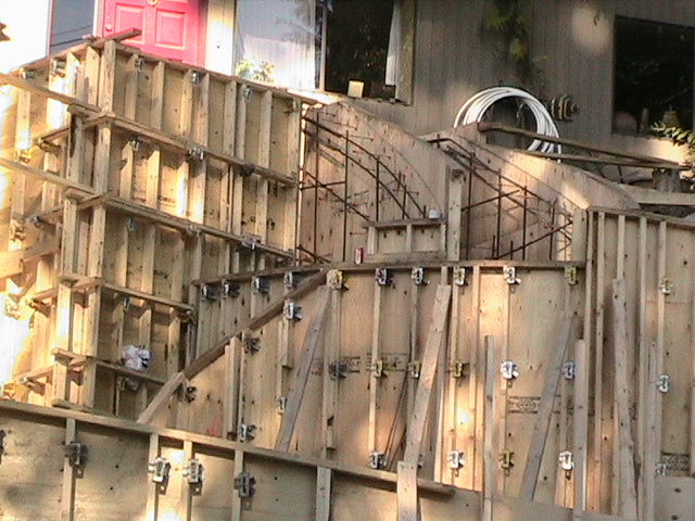
here is an example of a sloped form. the radius can easily be done if the top of the form is stepped. simply by matching the top plate radius to the bottom plate radius and building it in steps.. when it is sloped however like in the picture, the radius of the top plate changes.
In the doing this paticular job, the top plate radius was achieved by plumbing the studs off the bottom radius plate and working off of that to find the new radius.
there must be a formula that factors in the degree of slope with the base radius to find the sloped radius. anyone know of it?


Replies
If what I'm looking at is a descending spiral form as in a curved stair, I can help, but I can't answer your question specifically because I use geometry when confronted with this kind of challenge. To build the form, lay out the radius of the plates on the deck with a trammel. Cut out a top and bottom plate. Next determine your starting and stopping points on the radius and then divide the radius into equal segments of about a foot, more or less. Use this as a layout for a stud wall and build a curved wall. Now you have a portion of a cylinder and you need to determine the slope. Take a stick of lumber, a 2X4 works great and layout a storypole, dividing the total rise into equal parts - seven or so inches for each segment. Next stand the layout stick up plumb next to your curved wall and level over the marks from the story pole to the studs on the wall. The lowest mark on the story pole corresponds with the first stud - the one closest to the starting point and then the second lowest mark on the storypole to the second stud and so on. Now you can take a flexible rip of1/4'' ply and mark your curve. In the case of your form it looks like you might want to sheath the wall, layout plumb lines corresponding to the studs and then level over the marks from the story pole, this way you could cut off the sheeting at the line of the descending curve right on the wall. There is more: when you have a staircase the curve on the inside radius is smaller than the outside. The curves have the same center point, but are obviously different distances from it. This means the storypole for the rise stays the same for the inside radius wall and the outside radius wall but the top and bottom plates are different. When laying out the plates just determine the inside - or outside radius, whichever is easier and then add or subtract the width of the staircase on your trammel and swing the radius of the other plate. And repeat the above process.
thanks quicksilver...what I was looking for was a mathematical solution to acheive the radius of the top plate for the form which is not the same as the bottom plate radius, because it follows a sloping plane.
looks like Joe got it with the Helix calc.
thanks again quick for being 1st on the scene :)
I’m not sure I completely understand your question, but it looks like you just need the equation for an ellipse. Attached (hopefully) are the formulas for an ellipse & a diagram. If I missed the target let me know & I'll try again unless somebody beats me to it.
bd....and Piffin.
no it is not an elipse. others have used the spiral stair to describe it, which is essentailly what it is.
I know the picture doesn't show it so well, from the angle of the shot it is kinda hard to see the radius of the sloped section of form.
if you are familar with radius formwork you know that obviously top plates are normally the same as bottom plates, as with any regular form. but as soon as you make the top plate slope the top plate radius changes. the radius of the wall itself does not chage - only the top plate as it follows the curved and sloped plane at the same time.
EDIT: I just read Joe's post, I belive it is a Helix
Edited 11/25/2006 12:16 pm ET by alrightythen
"top plates are normally the same as bottom plates, as with any regular form. but as soon as you make the top plate slope the top plate radius changes. the radius of the wall itself does not chage - only the top plate as it follows the curved and sloped plane at the same time."
Just stumbling along this brainteaser...I am close to a math failure, but the subject is interesting.
With a sloped top plate, and a flat bottom plate, I'm seeing that for every linear inch of sloped top plate, there's more curvature than for each corresponding linear inch of flat bottom plate. So the top plate radius is tighter relative to the bot plate?? I guess it has to if the stud layout and wall radius are constant.
Sweet project, ain't it?
Edited 11/26/2006 2:51 am ET by Pierre1
Pierre,
you totally have the right idea, only the radius increases, instead of getting tighter - you simply have it backwards.
get a can of soup from the cupboard, look at the radius of the can - or better yet, take a strip of paper about 1" wide ang long enough to go half way around the can. holding it around the can, then slide the paper so the it angles on a slope, it is easy to see once you hold it on an extreme angle that the radius has increased.
some things are hard to visualize, I always find it easier, if I try to picture an extreme version of it.
PS..yeah it is quite the project, I have done plenty o' curved forms for this contractor in the past. we were always able to step our forms though therefore being able to work with constant radii.
if you want to check out his website his home page shows a giant curved planter, this was the 1st radius project I worked on with the crew I was with at the time. http://www.pinklotus.ca
Edited 11/26/2006 11:22 am ET by alrightythen
here's what I mean
View Image
View Image
you can definately see that the radius is tighter before you slope it.
If you want to define the shape mathematically, look into analytic geometry since that's all A.G. is. The definitions are part of what is causing so many solutions to be offered here. A radius applies to a circle or arc. A true ellipse is formed by the intersection of a plane and a cylinder. A helix is a downward progression through a cylinder with respect to the rotational progression (think of screw thread). I googled the word when I wanted a definition and there are a lot of hits when analytical geometry is entered. You may find exactly what you're looking for. If not, and you know an engineer or engineering/math student, it'll be a good question for them because I haven't taken a math class in almost 30 years.
"I cut this piece four times and it's still too short."
Thanks highfigh for all your great input. I'm usually a hands on guy that likes to figure out a lot of things using a hands on field approach.
however, it really is satisfying ( and sometimes quicker) to sometimes know why and how something mathematically works. I did a search on helix and came up with a site that showed a visual representaion of it. But I was having comp trouble and couldn't create a link for quicksilver to look at. but esentailly the barber shop pole desribes it pretty well.
could it be an elipse you are desribing?
Welcome to the
Taunton University of Knowledge FHB Campus at Breaktime.
where ...
Excellence is its own reward!
If you mean a helix, here's a Helix Calculator. There is a link below the calculator, "Baluster (Handrail) Radius Formula", showing the geometric development of and formula for the Radius of Curvature.
Or are you saying the radius changes as it travels upslope? This sounds like it might be a loxodrome (a spiral on the surface of a sphere) or something similar. The best move is to parametrize the equation; click on the "Vector Formula for Radius of Curvature" link below the Helix Calculator to see what I mean.
I don't have this method of analysing spirals handy for anything other than a helix but I'll see if I can Google a link for you later.
Joe Bartok
Edited 11/25/2006 10:55 am ET by JoeBartok
Edited 11/25/2006 10:58 am ET by JoeBartok
Edited 11/25/2006 10:59 am ET by JoeBartok
A link to a Spirals Web Page with parametrized equations of the curves.Joe Bartok
way to go Joe!
I just looked at the formula, and I think you nailed it with the Helix!
Can you add a pointer to the place in the photo that has the curve? You may be referring to a hyperbola or parabola, if you're looking at a conic section. If you're doing a circular stair, it is a helix, just like a bolt thread.
Here's a link to conic sections and google has other links for helix and other shapes in analytical geometry. http://www.answers.com/topic/conic-section
"I cut this piece four times and it's still too short."
Edited 11/25/2006 12:24 pm by highfigh
Edited 11/25/2006 1:06 pm by highfigh
Highfish: I can't find the link.Joe Bartok
Sorry, I forgot to plaster it in. http://www.answers.com/topic/conic-section
"I cut this piece four times and it's still too short."
Thanks. Now I have to do some research.
A few months ago I tried a making a version of the helix calculator using an elliptic cylinder. If the height is set to zero, in essence creating an ellipse in one plane, it gives the correct value for the (variable) radius of curvature, an astroid. The numbers can be also be checked using calculus. Making the cylinder circular and assigning any height also returns the correct radius of curvature.
This strongly suggests that the math and code are doing their job. But if I make both the central column an ellipse and assign a value for the height I'm screwed. There's no way I can develop the curve in two dimensions.
So ... it's time to go study.
"what I can do is take a shot of the plan so you can get an idea. standby I try and do it quick and post before gotta take boys to swimming lessons shortly. if not I'll get to it tonight."
I'll stick around as long as I can. I'm on the computer at the local library and we're all going to be "booted" out of here soon for the weekend so I might not get a chance to view the drawings until next week.
Joe Bartok
Edited 11/25/2006 1:23 pm ET by JoeBartok
Edited 11/25/2006 1:27 pm ET by JoeBartok
here some plan pics...hopefully Joe can check em out next weekend if not sooner.
View Image
the stairs you see at the top are what you are looking at in my earlier photo. I also included a close up,as well as an elevation. this driveway is the frontyard on side of mountain. so most everything is sloped.
Alrightythen, I'm still online for another ten minutes; only had a really quick peek at the drawings.
If you have a radius in plan and the slope in elevation is constant then a helix it is, and that radius of curvature formula is what you are looking for.
EDIT: Actually two radii of curvature, one to the center of each sloping retaining wall radius.
Joe Bartok
Edited 11/25/2006 3:46 pm ET by JoeBartok
Edited 11/25/2006 3:49 pm ET by JoeBartok
yeah thats what I thought when I read your 1st post and looked at the formula...dude you rock! thanks.
If you need the radius and it wasn't specified, you'll come really close if you project the line for the tread noses toward the inside of the arc. The point where they meet is the center and you can measure from the plans.
"I cut this piece four times and it's still too short."
yes that will give me the 2 dimensional radius, but not of the sloping top plate.
I do like that trick though. hadn't thought of that one. I have an old set of plans. I believe the new set has all the radius specified, but I know that they have also changed according to site.
I had plans once with ellipses drawn for wall opennings.
I sent them back to the archy telling him to place the necessary mathematical description of his curve if he wanted it built right. He didn't even begin to have an idea what i was talking about, "Can't you just make it look like I drew it?"
Welcome to the Taunton University of Knowledge FHB Campus at Breaktime. where ... Excellence is its own reward!
lol...that's too funny.
They get out their flexible bendy ruler thingy draw something and say build it.
I've laid out lots of curves for Architects, and I don't see any curve data on these plans. You should have a radius, delta, tangent, chord, and arc.
A compound curve, either horizontal or vertical has a common PC (point of curvature), a PCC (point of compound curvature), and a PT ( Point of tangency).
The curve begins at the PC, the compound begins at the PCC, and ends at the PT. All radiuses are perpendicular to one another, that is to say radial from the radius point(s). Spiral curves also, with a decending amount of arc and radius at specified points on the arc.
Vertical curves, as in road surfaces, are usually parabolic curves.
To set that up, we'd usually set offsets to the PC, PCC, and PT, with offsets to the outside of the construction area. The chords for intermediate grade points can be two-taped in provided the architect provided coordinates so they could be inversed.
Architects just need to provide builders with more information, and quit treating people like dumb-azzes.
Every once in a awhile I come across a thread where I'm totally in awe of how much smarter all you guys are than me! This is definitely one of them.
I'm trying to follow along, but I think I've just sprained my brain. But a very cool thread none the less. Thanks to you guys who are smart enough to process this stuff for letting knuckleheads like me eavesdrop on some very cool stuff.
You guys are ridiculous.View Image
this is an old set of plans. I beveive the new sets have the radius on it, but not the sloped radius.
On spiral and elevated curve work, it'd be nice if the arch or engineer would provide a orthographic or 3-D view showing the radiuses and grade breaks. Be easier to visualize, stake, and construct. It's no problem with newer CAD and powerful computers....
I thought about this a bit more over the weekend. If there's a significant width between the forms you might consider a layout employing four radii of curvature.
I made a model of a helix using a tissue paper roll (oh boy! I expect to see some comments on where the math is coming from ... nyuk! nyuk!):
Sketches and Formulas of Helix
The radius of curvatue was based on the cylinder diameter. But - the diameter of the outside of the ring is greater and I should have calced another radius of curvature instead of a two concentric circles. As a result the helix on the model I made actually twists as shown in the drawing.
Another thing I could add to that calculator in future is the tangent, normal and binormal for the helix. Would this information be of use in the field? If so, I can post the formulas.
Joe Bartok
Edited 11/27/2006 8:42 am ET by JoeBartok
keep the info and links coming Joe....dont' you love this stuff that makes you "think for the weekend"
just can't stand it when I can't sleep at night cause brain wont shut down.
Yeah, I know what you mean. I've lost lots of sleep.
I will try and get back with those TNB formulas later today or tomorrow. I think this is what TomT226 is talking about. Or maybe they're posted on a website out there on the Internet somewhere?
Joe Bartok
Edited 11/27/2006 10:56 am ET by JoeBartok
Edited 11/27/2006 10:57 am ET by JoeBartok
Jeez, I'm "losing it" ... I could have posted the formulas earlier.
Vector Formula for Radius of Curvature
The tangent and normal to the curve are the velocity and acceleration vectors respectively of a particle moving along the curve of the helix.
v = – r sin t i + r cos t j
a = – r cos t i – r sin t j
Not likely you need the binormal (perpendicular to the plane of the tangent and normal). As I recall that's the denominator in the formula in the link, determined by the vector product or cross product of the velocity and acceleration vectors: v × a
Joe Bartok
Edited 11/27/2006 2:02 pm ET by JoeBartok
Edited 11/27/2006 2:03 pm ET by JoeBartok
yeah...that would be nice. save a lot of time in the field.
whats a easy way to add a pointer to the pic? if you can tell me how to do it I will.
in the mean time...the 2 walls with therebar exposed are both such walls. ( stairs will be going inbetween them. then just below you see another sloping wall. that is the lower section. there are more but this wa s the best shot I have. I have some video that I can convert to dig pic , but I have to find the tape.
what I can do is take a shot of the plan so you can get an idea. standby I try and do it quick and post before gotta take boys to swimming lessons shortly. if not I'll get to it tonight.
highfish...just checked out that link...cool link.
that all deals with cones - this deals with a cylinder. so yeah the helix seams to be the one. man I sure don't remember any of this from school....20 years sure flies!
so much for the kids thoery "I'll never use this stuff". you will - just not for 20 years!
Edited 11/26/2006 11:38 am ET by alrightythen
If you're trying to find a way to lay out the circle, why not drive a pipe into the ground at the center and make it plumb, then slide another pipe that's slightly larger over it and attach a line to it. Since the grade will have been established, you could have one person raise the pipe to keep it level (using a string level) while the other scribes the ground. You won't even need a pattern then, other than for where the steps will go.
"I cut this piece four times and it's still too short."
I have reread the thread. I was pondering the problem and I think I came up with a solve that is field applicable. Looking down in plan view you should be able to determine the radius of the staircase you're using - the bottom plate in this case. Then looking at an elevation or determining the total rise from the architectural plan you can determine the hypotenuse of the stair, the angle of the rise. Essentially we are taking a cylinder and taking a slice through it at a certain angle. Now if we were to look at the slice through the cylinder from a 90 degree angle we can see that the x axis changes and the y axis stays the same. You should be able describe an elipse through with the original y axis and the new x axis. Am I correct or am I missing something. I had the revelation in the bathtub with my head under water, just the nose out thinking. Maybe I should take a tub to the field for these types of challenges. : ) Like hey what's he doing? Ah Don't mind him he's just thinking.
Edited 11/26/2006 12:55 pm ET by quicksilver
yes this is one of those things that you really have to be looking at it the right way.
it is almost, almost -so close to being almost - an elipse. but it is not. if you picture it as slice thru a cylinder as you have done, then it would be an elipse.
where it changes is that with an elipse, the curve turns on itself and starts to climb back up. making the curve much tighter at these points ( top and bottom of curve)
it's best and most common visual apliaction is that of a spiral staircase as was mentioned earlier. look at the pic of the can that I posted to Pierre. I almost fooled myself by imagining that the paper makes the turn at the bottom climbing back up around the can, making it an elipse. but you have to look it, that the paper continues down the can, creating a constant spiraling radius - like on a barber shop pole.
The fact that it continues to move downward instead of upward is the reason I think my method with the pipe and line will work for this as long as the line remains level.
"I cut this piece four times and it's still too short."
I fullly understand the premise of the pipe, but sure how practical it is in application.
when the walls in 1st pic were formd. the studs were simply plumbed off the base plate. one can string a line from top elevation to bottom elevation. then measure the string as a bottom chord, from there measure height from centre of chord (from chord to wall) and work off of that, to calulate the radius.
my goal, with this thread was to find a way to calcualte it knowing the horizotal radius and the slope in degrees. Joes find with the online calc for a helix looks like the jack pot. I still wouln't mind knowing the paper calcs, as well. but I'm sure I could look that up, now thatI know what I'm looking for with the Helix.
Edited 11/26/2006 1:42 pm ET by alrightythen
I've approximated a radius for this type of stair by using a chord measurement. Drag a tape between the outside corners of two treads as far from each other as you can reach keeping the tape straight. Then measure from the middle of the chord to the arc. While not exactly a circle, it's close enough in many cases, and the formula is http://mathforum.org/library/drmath/view/55037.html
In each case I was doing a pipe rail, and the pipe had enough flex to work perfectly. On the one, even got lucky in that the outside rail and the inside rail had the exact same "radius", which helped with the pipe bending. This wouldn't work for a true spiral, but I was doing about 45 degrees with each segment and it worked fine.
thanks for link cloud....that is great formula! I knew that formula exists, had it before, but had misplaced it. if you jump to the last part, that is all that you really need to know, and shouldn't be too hard to remember.
I'm not sure - I would have to go to my library and check - but I just got a reprint of a 1913 book on stairbuilding from Lee Valley, and I think I saw something like that in there.
Not that it helps now, but ...
Quality repairs for your home.
AaronR Construction
Vancouver, Canada
Thanks Aaron....yeah Lee Valley has some cool old books like that. I actually need to see if I can get some magnet catches for a cupboard door from Lee Valley- I'll check out the book.
Hey, buddy, you at home for the same reason I am?
I can get on to the main roads here in Vancouver, but I can't get to the job sites.Quality repairs for your home.
AaronR ConstructionVancouver, Canada
lol...yeah I got over a foot out here in mission.....I keep promisng to take my boys sledding down the local hill. but I don't really even want to go out.