Hi all,
I’m trying to figure out how to connect a light set using three way switches. It’s 4 lights in serie with two switches in the end, with the power coming in through the lights.
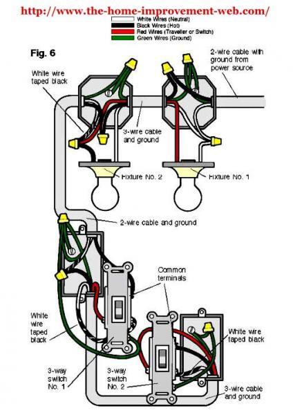
Now I have a great picture here from the www.the-home-improvement-web.com (I truly hope this is enough as a reference for using the picture) but it only has two lights. What happens if I need four? My hunch is to let the red traveler continue asin fixture one…
A would certainly appreciate your help here.
Nicoman


Replies
That diagram may or may not help you - Depends on how you run your wiring. There are lots of different ways to do it.
My suggstion would be to break it down into steps to make it easier to follow.
First - Run the hot wires to the first switch.
Then run 3 conductor wire to your second switch.
Then run from the 2nd switch to your first light fixture. Pigtail your wires, and go on down the line.
Make it as simple as possible, but no simpler. (-:
Around here the inspector apparently will not approve 3-way wiring that goes thru the light as that diagram shows.
Never heard of anything like that. What's the reasoning behind it?
Perhaps the meek shall inherit the Earth, but they'll do it in very small plots . . . about 6' by 3'. [Robert A. Heinlein]
What's the reasoning behind it?
If it's for similar reasons given "around here" it's because the elec inspector sees too many two conductor through-the-light instead of three conductor. So, to make the BI process simpler, just don't allow any.
Which makes it hard to argue against, as the electrican has to argue against "book" practice of running travelers to the switch(es), and then to the loads.
So, the appeal has to be made for the specific case, which becomes CYA for the BI & his department.Occupational hazard of my occupation not being around (sorry Bubba)
Bosshog,Seems a bit like that's the way it's been done. I've made a little drawing of how it looks now, but it just doesn't seem right to me. In fact I think I connected one of the white ones wrong.To add to the confusion the first switch has a side single pole switch to a small side fixture.Nicoman
http://www.danswiringpage.com/diagrams/3w_2lt_pfl.jpg
See if this helps.
Bob
Thanks for the picture, Bob. My case is a bit different though, take a look at my picture above.Nicoman
What wiring method will you be using?
NM, Romex, MC, EMT.
Running cables makes one way easiest while running conduit, where you can easily vary the number of conductors, makes another way easiest.
The diagram is obviously showing it run in conduit.
It's BX, with the ground in the shield. It's basically installed the way you see in the picture, the only thing I can affect at this point are the wiring in the switches.Nicoman
I think I may have found my thinking error, it looks like I mistakenly swapped two white cables.I've attached a new picture and marked my potential mishap in blue. I would be very grateful if someone knowledgeble could take a quick look and confirm.Thanks for all help so far.Nicoman
Your second diagram would work. The first diagram had a switched neutral or white wire. I would question changing the color from red to black in the first switch box though.
The DIY illustration confuses things with the inclusion of the green [?] grounding wire. What program did you use to draw your pictures?
~Peter
Thanks for confirming, it feels right now. Was a bit confused by the three wire between the fixtures at first but it now makes sense.Not following you on the switch from red to black? By using a red traveller I have to switch to black I guess.The first picture (with the green grounding wire) comes from a web page, http://www.the-home-improvement-web.com, and the ones that I've drawn was made in Illustrator. Not really suitable for drawing cables, a bit of a pain, which I assume was part of your question.Nicoman