I’m building a window seat and want to elimate a receptacle (never used it anyway). One solution of course is to simply buildover the thing but then if somewhere down the road the receptacle fails the whole circuit in that part of the house may be down.
If I take the receptacle out, is reconnecting the wires as simple as wire nutting the two hot wires together (black ones I think), wire nutting the two neutral wires together (white ones I think) and clipping the ground wire?
I know, pretty basic question but I want to be sure I’m not overlooking something here or even if there’s another solution. And as background, the receptacle is not at normal receptacle height. It would be a little bit above the seat where nice beadboarding will be so the issue is part safety and part aethestics.
Thanks!
Doug


Replies
Don't bury a junction box.
The reason is as you say-somewhere in time a poor connection could stymie someone from locating the problem.
Is there any slack in the wire feeding that outlet? You could maybe raise it so a cute little christmas tree could be placed there in season?
You can't "bury" a junction
You can't "bury" a junction box (or a receptacle) -- they must remain "screwdriver accessible".
Have you checked whether the receptacle "feeds through" or not? If not, go to the location that feeds it, disconnect the wires, cut them off flush with the cable jacket, and push them out of the box. Do more or less the same at the problem receptacle, and then just "abandon" the cable.
If you have wires continuing on, however, you must somehow install an accessible box. This could be below the seat level if you arranged for some part of the seat to be removable for access.
But note that if you move the box lower you may not have enough wire length for the connection. Often it's necessary to install two boxes a few feet apart to provide some slack.
When you reconnect things (in a box), be sure to connect black to black, white to white, ground to ground.
It should be noted that, by removing the receptacle, you could be creating a technical code violation. Code requires that, in most rooms, a receptical be no more than 6 feet away from any point along the wall.
Dan
in most rooms, a receptical be no more than 6 feet away from any point along the wall.
Is this correct? I've been really mistaken if so. Been working under the assumption that distance between was 12', continuing the measurement around the corners of rooms. No more than 4 or 6' out from the corner. Kitchens of course an exception.
Same thing
"Distance between receptacles = 12' maximum" VS "no point on a wall is greater than 6' from a receptacle".
The two statements are both correct and produce the same result.
Jim
Gotcha
My comprehension levels are low. At first reading I took it to mean that max distance was 6' between recepts. I now understand that if I stand between the recepts 12 ' apart, I only need 6' of cord on my device.
thanks for the enlightenment.
>>>At first reading I took it
>>>At first reading I took it to mean that max distance was 6' between recepts. I now understand that if I stand between the recepts 12 ' apart, I only need 6' of cord on my device.
One other point about this. The rule, at least around here, only seems to apply to residential construction; commercial is immune, which has always surprised me.
Yes, I know it would be silly to have plugs every 12' in hotel hallways, auditoriums, and arenas, but I've been stumped numerous times when doing some sort of presentation to a group, and there wasn't a plug in miles.
and there wasn't a plug in miles.
Scott,
Makes the drywall go up faster.
There's a subtle difference -- the 6' rule handles end-of-the wall situations. The way I like to think about it is that you should be able to place a floor lamp with a 6' cord along the wall anywhere in the room and have it reach a receptacle. (Of course, the cord can't cross a doorway, and there's an exemption for short wall segments under, I think, three feet.)
as simple as
since ya had to ask, must not be, huh?
Me, I'c bury the box, but crimp and solder the connections and cover with an Ideal rubber boot vs. a wire nut (which may fail sooner or later). Crimped and soldered will not fail during the life of the house (IF you know how to solder copper WIRE).
But, since yas aint me, better follow Dan's advice.........
What's under the floor?
A bit more info on the receptacle location might be helpful......
If the receptacle is a "dead end" or "end of the run" the solution becomes easy - find the box where the one cable is fed from - clip cable at feeder box, shove cable into the wall - same at the receptacle you want to eliminate. Bury / remove the now non-functional box at will.
If the box feeds through (more than one cable present) the situation becomes more complex as you must maintain the circuit and the splices must (code) remain accessible.
Your receptacle is below a window, what is below the floor? Might be possible to pull cables down and junction them in a box below in your basement or crawlspace. Might have enough cable to pull cables down and get them into a floor outlet box.
Or in the another case, where Box 1 is the upstream box, Box 2 is the box you want to eliminate, box 3 is a downstream box. You might be able to remove / abandon Box 2 and both of it's cables by fishing a new cable from Box 1 to Box 3.
Lots of options depending on your specific situation........
Jim
Thanks guys for all your input. You're great.
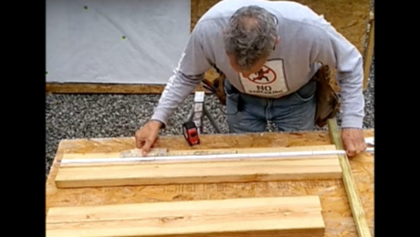
I'll attempt to attach a photo in this new forum format. The offending receptical is shown and actually there's two, another one off to the right just out of the photo. I guess I could try to lower it so it's under the seat and then cut a hole in the back of the cabinets that are going below the seat. It doesn't appeat that there's any slack in the wire and there's another outlet "downstream" (actaully there are two more outlets on each side of the seat so I have four outlets in about 21' of wall).
The window seat has always been planned so when we built the bouse three years ago I had the sparky's set these two outlets up higher then normal. Probably a mistake as now when I'm doing the project they won't look all that great against the nice beadboard.
I came across this: http://www.tycoelectronics.com/catalog/bin/TE.Connect?C=11621&F=0&M=CINF&GIID=1394&LG=1&I=13
but it wouldn't be accessable.
Thanks again.
Doug
You should have thought about this before you put the beadboard up. Then it would have been a simple matter to poke holes in the wall and reroute the wires.
Still may be the best route to go, though.
The AMP connectors are "approved", but many electrical inspectors won't approve them, plus they still have to be accessible in most circumstances.
But you may want to think about installing some of the beadboard with screws, so it can be removed.
Ya know, while thinking of that in the last hour or so, that's what I was thinking. It looks like each outlet falls on a waincot joint so I take two waincot pieces, glue them together, cut off the inward piece of wood on the "groove" side, on the other side slip the tongue of this "door" in the groove on the wainscoting that's attached and glued to the wall and swing it closed. The whole thing is only 13" high. There's a 3/8"X 1 3/8" stop going under the window stool but I could cut that and the bottom doesn't really matter because there's going to the seat cushion there.
Agreed on the waincoting install but I was plannning on living with the receptacles until I got that far and thought "Damn, that beadboard is going to look really nice when painted up all pretty and those recepticals are going to really stand out.".
Doug
painted up all pretty
You really should prime (tinted) so when the beadboard shrinks (moves around) any gaps in the T's & G's will still show the color.
Maybe. But this is all material left over from when the house was built 2 years ago. Even that stuff, while not benefiting from 2 years of "conditioning", looks great.
Doug
That's definitely good advice wherever a dark color will be used on T&G. Also good when installing sheet paneling -- stain the studs/furring behind the joints.