What you have there definitely doesn’t look good to me. Another set of “coller ties” 1/3 of the way up from the plate doesn’t sound much better.
Gravity is trying to pull your ridge down, which would force your walls to spread. The coller ties you now have, and even the others you describe will stay horizontal, but gravity will still pull them down over time, putting a reverse crown in your rafters.
Buck up and hire an engineer. She’ll be able to tell you the least painful way to rectify what you have now. That’s what I’d do if a customer asked me to deal with a roof framed like that.


Replies
Hi Mike
Whats going to stop the side walls getting pushed out? Is the ridge a structural beam? Collar ties are normally no more than a third up.
With the frame you have I would expect a series of large "triangles" to form the roof frame. I suggest you ask an engineer to confirm.
Whats your location?
Edited 12/2/2008 10:08 pm ET by USAnigel
"Collar ties are normally no more than a third up."common misperception.Rafter ties are no more than a third of the way up and do the work of preventing wall spread in the absence of a structural ridge.Collar ties, by definition, are placed in the upper third and the work they do is to prevent high winds from hinging a roof open or splitting it at the ridge.
Welcome to the Taunton University of Knowledge FHB Campus at Breaktime. where ... Excellence is its own reward!
Thank you Piffin, rafter tie is what I were thinking.
How about a "beam" on its side to stiffen the wall at the top plate and prevent spreading. It would need lots of tying together but would keep the space open.
Where's that engineer when you need him?
Thank You all for your advice with my problem.
I spoke with my inspecter and he said that the 4x6x18' anchored in the slab to the 2x10 ridge beam would pass his inspection and be safe. He could not tell me what to do but as a retired contractor he said thats what he would do and still have room for the lift.
I will buy the beams tomorrow and install them when I get a lot of strong back and weak minded people.lol
Thanx again,
Mike
So your beam is going to span 38'?
And your beam is going to be one 2x10?
I see something wrong with this picture.
ANDYSZ2WHY DO I HAVE TO EXPLAIN TO FRIENDS AND FAMILY THAT BEING A SOLE PROPRIETOR IS A REAL JOB?
REMODELER/PUNCHOUT SPECIALIST
along with 2x8s 16" oc and 2x6 collar ties
are your 2x8's your ceiling joists?
The problem I see is that you need a seriously huge beam.
my beam was 3 2x16" laminated beams bolted nailed and glued .
and my engineer said that to span the full 40' would require a steel beam as no lams out there could resist the deflection.
ANDYSZ2WHY DO I HAVE TO EXPLAIN TO FRIENDS AND FAMILY THAT BEING A SOLE PROPRIETOR IS A REAL JOB?
REMODELER/PUNCHOUT SPECIALIST
Yes , they are my joist. The inspector said 16"oc would be fine as long as i installed the 2x6 collar ties.
I did and now I'm gonna install 4x6x19' post every 5' anchored from floor to ridgebeam.
He said that would be ok also.
Thanx,
Mike
So you are putting in a post every 5' from ground floor to underneath ridge.
Do you have foundation footings through the center of building.
Is this going to mess up your garage and second floor space?
ANDYSZ2WHY DO I HAVE TO EXPLAIN TO FRIENDS AND FAMILY THAT BEING A SOLE PROPRIETOR IS A REAL JOB?
REMODELER/PUNCHOUT SPECIALIST
Everyone else pretty much covered the building aspects, but if you don't mind I'd like to bring up a question of use of terminology. You said:
>> I did and now I'm gonna install 4x6x19' post every 5' anchored from floor to ridgebeam. <<
A 2x10 is not a ridge beam. It is a ridge board. A ridge beam, also known as a structural ridge has solid support at either end all the way to the foundation and is sized so as to be able to resist deflection. As stated above a beam able to span 38' (or what ever it was) would have to be pretty hefty - you would likely need a crane to set it in place. A ridge board is more of just a place holder that gives you something to nail the top plumb cuts of your rafters to and also helps absorb some minor mis-allignment between your rafter pairs.
BTW - my sis lived in a house that was framed similar to yours. Granted it was rather old - maybe 70 years but the walls were pushing out badly and the ridge was rather "sway backed". They got an engineer to prescribe a fix and the 'fix' was demolition.... It was condemned. The house was loaded into demo trailers with a track hoe and taken away.
How about another solution. Not knowing the final set up so just throwing something out here. You have probably a 37' span at the ridge, how about a full height wall centered under the ridge that would be say be 12' long and supports the ridge and then two other shorter structural ridges at 12'6" ea. at the first and last thirds of the depth of the garage? One wall instead of posts every 5' seems to be a more user friendly environment. Should leave room for car doors to be opened at the entry end of the garage and work space and lift where the wall is.
They can't get your Goat if you don't tell them where it is hidden.
Seems like the structure went from nothing holding the ridge up to an awful lot of overkill. Still no real engineering.A Great Place for Information, Comraderie, and a Sucker Punch.
Remodeling Contractor just outside the Glass City.
http://www.quittintime.com/
Yea your right about that. My idea sucks anyway (shouldn't be trying to be analytical when down with the flu!) the wall I suggested would need a footing under it.
They can't get your Goat if you don't tell them where it is hidden.
>>the wall I suggested would need a footing under it.<<Maybe. Depends how thick the slab already is, and what the calculated load on the wall would be dispersed over the length of the wall. I still like my solution the best (intermediate timber trusses with structural ridge in between.) It keeps things open to the peak except for two trusses, and keeps the floor wide open.Steve
Yes - sounds like a "Let's do ANYTHING that satisfies the inspector, as long as we don't have to pay an engineer, even if the overkill costs three times as much and ruins the space"
Welcome to the Taunton University of Knowledge FHB Campus at Breaktime. where ... Excellence is its own reward!
I would have leaned toward the cables. Clean if it would work with his lifts. I've seen it done on some smaller dwellings with rod rather than cable. I suppose there's some engineering there too.
The soffit as flat box beam does sound interesting. I've done some beams but the spans weren't near as long. Have no idea how the loads compare from down to lateral. I'm certainly just a dumb carpenter in this one.
But that 6 of 'em there thought that original layout was good is surprising.
Methinks he should have built a pole barn in the first place.A Great Place for Information, Comraderie, and a Sucker Punch.
Remodeling Contractor just outside the Glass City.
http://www.quittintime.com/
I have often wondered if a soffit overhang could be engineered to act as a load resisting flat beam of if it would just be too expensive to do in comparison to more time tested methods.
Welcome to the Taunton University of Knowledge FHB Campus at Breaktime. where ... Excellence is its own reward!
Makes sense to me but in this case the walls are very long and a major "laying flat" beam will be needed.
That's what I was getting at with my top plate/horizontal beam/loft post.If the ridge doesn't drop, the walls don't spread.But if the walls don't spread, the ridge doesn't drop! Who cares how you get there?So here's the perfect combination of our ideas, Piff:Soffit overhang as large as you can get away with. Soffit OSB "underlayment" glued and screwed.Soffit lookouts cantilevered back into the interior of the garage to create 3' to 4'w perimeter loft, w/loft floor consisting of multiple staggered ply layers (2x 3/4"? 3x 1/2"?).The weak point in this construct would probably be the rafter birdsmouth: structural ridge, and it just sits there. Structural plate/soffit, and it has to resist the outward thrust.Starting from scratch, we'd just deepen the birdsmouth so that the bottom edge of the rafter met the BOTTOM of the top plate.Retrofitting, we'll have to add some framing angles to assist the birdsmouth toenails. Shouldn't be a problem, but this stuff depends on the engineer -- sometimes you come up with a cool, simple solution, and butt heads with an engineer who wants to calculate every fastener in the entire structure.Aitchkay
I'm sure this is a stupid question but...
If rafter ties are there to prevent the outward spreading of the walls couldnt the ceiling joists be somehow attached to the walls to serve the same function?
In a case like my house-long skinny with gable roof at both ends with a 12/12 pitch roof with a finished attic space where the floor joists are 2by10s.
Would it not be possible to use lag bolts or some sorta simpson bracket to attach the rafters to the floor joists to the top plate of the wall below to prevent spread? Would this not serve the same function as rafter ties?
Daniel Neumansky
Restoring our second Victorian home this time in Alamdea CA. Check out the blog http://www.chezneumansky.blogspot.com/
Oakland CA
Crazy Homeowner-Victorian Restorer
couldnt the ceiling joists be somehow attached to the walls to serve the same function?
You are right. Normally the ceilings joists are the rafter ties.
Beer was created so carpenters wouldn't rule the world.
Yes. The typical solution to this structural problem is to use ceiling joists which act as rafter ties. However, in this case, the OP has no ceiling joists because of his desire for open design. They are moved up so high in the roof structure that they only function as collar ties, not rafter ties
Welcome to the Taunton University of Knowledge FHB Campus at Breaktime. where ... Excellence is its own reward!
I have often wondered if a soffit overhang could be engineered to act as a load resisting flat beam of if it would just be too expensive to do in comparison to more time tested methods.
You just tossed out a visual nugget that connected a few dots for my current project!
It's an old house with ceiling joists running the wrong direction in one room so in the last 90 years the wall and roof framing in that one room spread out about 3/4" at the top plate in the center of the wall.
The house was originally overbuilt for the day, but they missed the boat with some unstandard framing: rafter ties 1' above top plates, end nailed into blocks between rafters rather than nailed directly to the sides of the rafters.
There is a big collection of mechanical/electrical gizmos, a chimney, 2 turdle doves and a partridge in a pear tree in this one section that makes the retrofit of new rafter ties cost prohibitive.
Since this fix is way outside the scope of what I'm really working on, it looked as if it was one of those things that was going to have to wait for the next remodeler 40 years from now.
As luck would have it, I am tearing off a poorly built soffit in this area of the house and don't see why I can't add a 16' horizontal LVL to the soffit to span this section and provide some long-term prevention to further wall spread without significantly tearing up the inside of the room.
The existing facia drops 6" in this section of the house and there's a full length gutter so a slightly taller facia is easy to hide. The old 1" rough cut soffit boards leave only 3/4" to allow for if a LVL is used on the soffit and I'll be the only one who will even notice it.
I didn't even see this fix coming, but I'm really glad you tossed that idea out.
Beer was created so carpenters wouldn't rule the world.
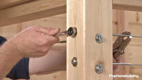
On the project I am currently working on there is a somewhat similar solution to a different problem. ICF walls 16' tall x 39' long, back filled to 10' in height. Need to prevent wall from buckling in from backfill load as well as from wind loading. Solution is a 39'x 3 1/8" x 19" glue lam laid on it's side and bolted to the top of the concrete wall every 2' o.c. with 12' x 5/8" anchor bolts as well as 4 3/4" bolts at the ends of the G.L. placed evenly across it's width.
They can't get your Goat if you don't tell them where it is hidden.
Bingo. As I've said, it doesn't matter if you deal with the spreading problem at the ridge or at the wall, and since it's already built, dealing with it at the wall is much easier and less complicated.AitchKay
That sounds like a pretty unique construction detail.... What kind of building is it? 10' of backfill sounds a little like a basement with 11' ceiling... Must be commercial.
Other than that, You said >>... glue lam laid on it's side and bolted to the top of the concrete wall every 2' o.c. with 12' x 5/8" anchor bolts ...<< Was that a typo???? 12'!!!!! E-gads!!!!
Yes commercial construction. 16' tall walls, 10' backfill perpendicular to roof framing. GlueLam is there to keep wall in place as one unit during high wind loads.
Site is very exposed to winds. 100mph. criteria. Prior to backfill I have to place bracing ( "Tilt Up" style braces) at about 8' o.c. And Yes a typo, should have read 12"x 5/8" "J" bolts 24" o.c. Hope to post the the latest pics of the project in the photo thread : Job Site View (Not much has changed except the walls are now all poured) http://forums.taunton.com/n/mb/message.asp?webtag=tp-breaktime&msg=106306.73
They can't get your Goat if you don't tell them where it is hidden.
When I took my GC test the "plans reading section" had test Qs based on an example set of prints - it was coastal construction.... Maybe 140 MPH wind zone - don't remember and too lazy to look it up. Anyway... the house had anchor bolts that went from the footers to Simpson brackets bolted to the roof trusses... That house wasn't gonna blow away....
that's a pretty typical detail where cadioli builds in australiaMike Hussein Smith Rhode Island : Design / Build / Repair / Restore
maybe a stupid Q but is Mark still around here? What is his screen name? I remember him posting pics here of projects years ago....
PS - I notice that the OP deleted his .1 post. I guess things weren't going his way here either.... :-) Not to minimize his situation.... sucks for him.
Edited 12/6/2008 7:18 am ET by Matt
no...only once in a blue moon....
bet he shows up at blodgetts thoughMike Hussein Smith Rhode Island : Design / Build / Repair / Restore
All.........Exterior Buttress ?
It's worked for thousands of years at Notre Damn Cathedral in France..
It's worked for thousands of years at Notre Damn Cathedral in France..
HEY - watch your language!View Image “Good work costs much more than poor imitation or factory product” – Charles GreeneCaliforniaRemodelingContractor.com
Yeah!That and his spellingand using foreign words around carpenters - that's just plain rude.besides, who cares a about dat other damn cathedral enyways?
Welcome to the Taunton University of Knowledge FHB Campus at Breaktime. where ... Excellence is its own reward!
I'm sure buttresses would work, but that would definitely require engineering around here.If he's going to consult an engineer, why not just go with the solution that is easiest/cheapest for the OP?
Jon Blakemore RappahannockINC.com Fredericksburg, VA
JB.............." why not just go with the solution that is easiest/cheapest "
Awwww .........come on :)......you know all really good reason's. Lets get together and move that house to the east 6 inch's ,just because it would be FUN to do thats why.........:)
We have a lot of that same stuff here, wind and seismic loads require sole plate to truss hold down connections.
They can't get your Goat if you don't tell them where it is hidden.
It does seem a little light on wall spreading support.
Around here you'd need to either add the rafter ties no more than 1/3 up from the top plate, or get an engineer.
Collar ties in the upper 1/3 are just to keep the tops of the rafters together and don't do much to keep the walls from spreading. The other carpenters are correct in saying what you have are correctly installed collar ties, but they don't qualify as rafter ties according to IRC, UBC or most commonly used framing practices.
The problem is the walls want to spread and you don't have much holding them in.
The code book can only cover so many situations, so when unique situations come up they differ to an engineer's design.
Personally, I'd call an engineer and he'll be able to give you options for fixing it.
Normally this type of situation is fixed with a load bearing ridge beam that holds everything up so the rafters don't put outward pressure on the top of the walls. It's easy to size off a chart and the idea is rather straight forward to carpenters and inspectors.
Otherwise...
Cable ties can be retrofitted to hold the tops of the walls in place if you don't mind the look of them. Heavy steel joists can be retrofitted to not project below your existing ties, but it would be expensive. Additional, probably larger, joists could be sistered to what's there. It is also possible, although not normally seen, to reinforce the top of the wall to resist outward movement, with a heavy beam tied in well at the corners.
Or.....whatever the engineer is comfortable with.
You might not need all that much additional work to pass if your snow loads aren't that bad.
:-)
Beer was created so carpenters wouldn't rule the world.
That roof is a problem. The code changed in 2006. Used to be rafter ties could be 2/3 of the way up from the top plate, but in 2006 it changed to 1/3 of the way up. You got bad information from the first guy. Your framing inspector is right. And you can just look at that roof and see it's not going to stop the spreading.
One fix--and I used this method with my own shop with the help of an engineer (see attached sketch)--would be to use two intermediate timber-style trusses and span the resulting 12' 4" between trusses with structural ridge. That would keep the floor clear and give you three separate 12' areas clear to the peak.
Steve
View Image
Edited 12/2/2008 10:48 pm by mmoogie
It doesn't matter what they said. It's 1/3 up from the plate. And there has to be big enough rafters or enough of them to resist deflecting and giving your roof a sag.
I think you need to put them 1/3 from the bottom.
Mike....I swear to you.....I read as far as here is a picture of the so called problem, looked at the pictures, and knew what you were going to say, before reading any further.
Those "rafter ties" are useless.
Hire the engineer.
J. D. Reynolds
Home Improvements
Looks like you got enough room for flying buttresses. As stated before, cables fore and aft of where your lift will be might work but the inspectors are going to want an engineers stamp on it.
Yes, an engineered cable tie solution might be the least expensive and most elegant at this point.
Welcome to the Taunton University of Knowledge FHB Campus at Breaktime. where ... Excellence is its own reward!
One more echo, if you have any snow load, or maybe even if you have heavy shingles, your garage is a prime candidate for collapse.
An engineer may be your cheapest out at this point.
As to the 6 carpenters who agree with you- they are wrong.
Jon Blakemore
RappahannockINC.com Fredericksburg, VA
Mike,
Do you still have those pike-pole braces along the sides of the garage? If not, I wouldn't be surprised if you measured at the middle of the walls, and found you had a couple inches of spread already.
Steve
Structural ridge shoulda been the first step, second option would be span rated scissor trusses.
Now, i would run a structural ceiling joist from front to back underneath the ridge and on top of your top wall plates (maybe steel beam)and stick supports up from that to the ridge. your lifts usually go in line with the garage doors and shouldnt be affected.
I'd vote for a structural glue lam ridge beam with continuous support to foundation, or two - one on each side of the window. Do it and you'll sleep better at night. I mean, people you love will be using this building, right?
Nice garage, BTW. Clean looking framing.
CaliforniaRemodelingContractor.com
I had almost the exact same issue this summer.
I framed the roof and braced on friday and came back on monday to find the walls spread and the braces pulled out of floor.
I used large ratcheting straps to pull the walls back and 6"screws to pull the plates down.
Without center walls there was nothing to keep the walls from spreading.
So 38' is too long for laminated ridgebeam.
I was lucky as I had a stairwell wall to support my tripled up ridge beam.
I had also put in very large footings in the foundation to support the steel beam that that supported my 30' span of I joists for second floor floor in the garage.
My wind braces went to the bottom of my original ridge on every rafter set using 2x8's then I cut a rectangle out of the front gable underneath the ridge and windbraces.
I built a plywood run on top of my ceiling joists and put runners on both sies to guide a dolly.
I then rented a large scissor lift and lifted each 16" laminated beam up and drove it in far enough to set on top of the dolly and rolled them into position.
I will be glad to give any help I can as I know how frustrating it is as my plans had no detail for the beam even though I qeustioned it and the homeowner did not follow through on the details with the designer.
ANDYSZ2
WHY DO I HAVE TO EXPLAIN TO FRIENDS AND FAMILY THAT BEING A SOLE PROPRIETOR IS A REAL JOB?
REMODELER/PUNCHOUT SPECIALIST
Mike I suspect you were going for large head room and don't want to give that up..
how about buttress braces?
goin on the inside from the vertical walls up to the rafters. about 1/3 of the way up. it achieves what they want without loss of headroom. I think I have a picture of what I'm talking about.. at 85891.1
while I made scissor trusses you could eliminate those and put in some of the buttress braces which ties the roof with the wall forming a triangle you'd lose a little shoulder room near the wall but retain your headroom and probably satisfy the inspector..
Edited 12/3/2008 9:54 am ET by frenchy
What is the ground snow load in your area?
What species and grade are your rafters?
Jon Blakemore
RappahannockINC.com Fredericksburg, VA
Here's one direction to point your engineer in:
The walls won't spread if,
1) They're tied together tightly at the corners, and
2) They can't bend.
So, 1) she can specify the appropriate steel straps to tie the corners, and,
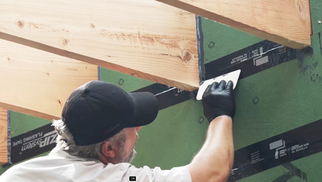
2) you can turn the sidewall top plate into a horizontal header:
This is easier to do before the rafters go up, but you can notch 3/4" ply around the rafters. At least two layers, with staggered joints.
Have her specify the fastening schedule, and since things have gone South with the inspectors, it might be safest to put one layer on top of the plate, and the other below, so that you can see all of the fasteners. And 2x between the layers, of course, running full length.
Knee braces can hold it all up.
You'll end up with a (3'to 4'?) storage loft at either side of the garage. That won't be so bad -- the middle will be completely clear.
Could you build your lift system into the roof and use those as the tension ties? The lateral thrust at the bottom of those rafters could be well above 300lbs per foot, and a two ply top plate will not stop the wall from bowing should the roof ever see full design loads.
You could add a horizontal beam at the top of the wall all around the garage. This would need to be sized to resist the lateral thrust at the bottom of the rafters and tied back to both the top plate and rafters. If you can add some ties accross the width of the garage that will help reduce the beam size. Just an idea.
In any event, you either need an eng to solve the problem or if you have the headroom, add the ties as suggested by the inspector. Its a simple engineering problem that really shouldnt be that expensive if you dont want them to evaluate all the possibilities.
Brad
You do need a structural ridge for that. It can be inserted under the existing ridge but will need support to foundation also. That might require some header work over that round top window to transfer loads.
As built, you would have wall spread and a sagging roof eventually.
as for the general Q, Yes, I have fought the inspector and won.
but I was right and he was wrong and I was able to show him in his own book. This is not the case for you. He is right.
It is unfortunate that you seem to have been given the wrong info at first.
Welcome to the
Taunton University of Knowledge FHB Campus at Breaktime.
where ...
Excellence is its own reward!
The inspector is right on the money. What did you submit to your permits office to end up in this pickle. The gable studs should be continuous from floor to roof and probably at least a 2x6. The collars are way too high, code books address this much better than 6 framers do and the sheathing on the front wall shouldn't be so pieced so it actually prevents racking.
Going forward, here is a rule of thumb:
Stick framed gable roof structures must either have ceiling joists (rafter ties) or a structural ridge.
Sure there are ways around it, like in your situation it may likely have worked if the rafters were upsized by an engineer, but the above is somewhere around building 101. Or you could have used scissors trusses.
BTW - Here, all structures are required to be engineered with the exception of small additions and decks. The engineer we use charges $.14 a sq ft for unheated and $.23 a sq ft for unheated so the cost would have cost between $150 and $250. See attached.
If it were me I'd be looking at dropping a ridge beam in the top. It's not extra expense, it's what was required in the first place to build what you wanted. Of course then the question arises if the foundation is built to handle the resulting point loads at either end of the beam. Which is really a Q for any of the other recommended fixes too. 4" or 6" of concrete isn't a foundation....
To tell you the truth, I'm pretty sure that that balloon wall framing wouldn't have passed inspection here either.
Edited 12/4/2008 7:19 am ET by Matt
Wow, the engineering rates are very reasonable. Those are not SE's (structural engineers) are they? I am a Canadian, but I guess that PE's can do simple structures in most states.
Brad
>> Wow, the engineering rates are very reasonable. Those are not SE's (structural engineers) are they? I am a Canadian, but I guess that PE's can do simple structures in most states. << Yes they are Structural engineers. When your plans are engineered you get them back with the engineering and a stamp of one of their PEs on your plans. I'm guessing they specialize in residential wood frame construction but am not sure. Here is their web site. They have engineered 90% of the houses I've built within the last 10 years.
Coincidentally, yesterday, I even received a sales brochure from them lamely disguised as a Christmas Card. :-)
The reason I posted the price list was not to suggest that anyone out of state use them, it was just to show people (with backup documentation) that if you find the right engineering firm having your drawing engineered and stamped isn't necessarily very expensive and is money well spent. What did I say - $150 to $250 for this project? Here anyway, plans are required to be engineered by an in-state engineer or architect.
You are lucky your inspector didn't call you on the gable end wall framing also. Sorry, I just opened another can of worms....