I’m starting to hand frame a roof with 15 hips, 9 valleys and three eyebrows. Every time I do one of these I’m blown away by the size of the hips. many are 3- 11-7/8″ LVL’s. The existing 6-12 roof we’re replacing was built in the 1920’s (like thousands of others) with 2×4 rafters and hips. The longer rafters are undersized and some sag, but the hips are straight and true.
It is obvious in looking at the headers and lumber spans in these older homes that not much engineering went into them, but one thing that did work was the hip roof, and the opposing forces that hold them up. The only sagging in these hip roofs that I have seen can be attributed to undersized jack rafters sagging on long hips, thus allowing the hip to sag slightly.
Why is it that today engineers only use simple load calculations to engineer hip roofs? Is it that the nail/fastener connections are more critical and too difficult to specify? I don’t understand the need for these massive hips. Please educate me.


Replies
Hey Woodtick...I feel your pain. I was framing a house this winter ...a bastard hip with a cathedral ceiling under a major portion. The engineer (who worked for the lumberyard) speced double 14" or 16" LVL's (can't remember which) for the hips. I tried to explain the problems to the builder...("well I can take a humungous seat cut out of them and jeapordize their structural integrity, or I can raise the height of the plates in the entire house, except for the corners, I'll have to lower your soffits of course....etc. etc.etc.) To make a long story short he just didn't get it so he called the engineer directly. Now I can't directly verify this myself, but he told me that the engineer told him that in their computer programs hips just don't work, no matter what they punch in, so some of the inexperienced guys would just throw out something massive to cover their azzes! He told me to go ahead and use 2x12's no problem and even came out and signed off on the plans. First time I ever had less work to do after a conversation with an engineer!
I have seem some hips travel massive spans where LVL's and bearing posts where speced that I didn't question in the least, however I do agree that, IMHO, many times the way that hips are speced out is total overkill.
Don't know if you saw the quote I posted a while back - "If you took all the engineers in the world and laid them end to end, they wouldn't reach a conclusion".
Seems to me there's a lot of disagreement over how ridge boards in hip roofs work.
One camp says that hip ridges work mostly as nailers - Just a place to nail the end of the boards to. (Like a ridge board on a gable roof)
The second camp says the ridges are structural, and actually support the ends of the jack rafters. (As if there were no ceiling joists)
Take your pick on which one is right.
My thoughts are somewhere in the middle. The older homes you mention are often smaller. So a ridge board might work fine. Some of the newer homes have much longer spans and higher pitches, which are less forgiving. So what worked on smaller stuff may not work on new homes now.
One thing I think contributes to the strength of a hip roof is the diaphram action of the sheathing. But there have never been any studies done on this, or any published research that provdes design values an engineer can use. (To the best of my knowledge) Since engineers rely on published design values, they can't just make stuff up and use it. An engineer in court who says: "Well, it looked good on paper and I thought it was O.K." would quickly be in deep stuff.
One thing I've always wanted to ask an engineer who calls out big hip ridge beams: What holds up the high end of the beam? Generally they don't have any posts under them, that I've seen. But the high end has roughly 2/3 of the load. (The longer rafters are near that end)
Of course, the obvious solution is just to use roof trusses...............(-:
Love is the triumph of imagination over intelligence.
Most engineers and most software do very poorly on hips and valleys.
Current roofs (plywood over solid lumber) get a great deal of strength from diaphrams - the roof sections act as panels rather than a bunch of rafters.
In a well designed and well built house the valleys can usually be 2x lumber with the depth matching the cut depth of the rafters.
Maybe they just don't see the big picture. People and jobs have been so specialized that even if you could people wouldn't listen to you because you're not a specialist of some sort.
I don't know if this will help, but here is a link to GP's span chart for LVLs that are to be used as Hips or valleys. There are seperate span charts for hips and valleys. You could double check your specs and call the engineer and ask him why there is such if difference if there is.
http://www.gp.com/englumber/pdf/123040/38-39.pdf
Tim, thanks for the table. I have their tables on headers, beams etc. but was not aware of this one, thanks! I think what is spec.'d is over-sized.
Hips and valleys in roof structures aren't much different from beams in floors, when viewed in structural analysis. Figuring out the tributary area of load can be a little more subjective, though. If engineered lumber was specified, you can usually get all the help you need in a sizing check, from one of the sharpies at TJM, or Boise, or whoever's LVLs will be used.
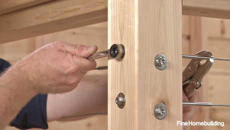
What about the connection to the top plate. My engineer spec'ed a custom bracket made from 3/8" steel. The base was "L" shaped to match the corner and each leg was 9" long. It then had vertical legs to match the double 2 x 12's . All bolted with 1/2" bolts.