I’m designing a front porch addition on my home and am looking for advice on the constuction of the deck due to several issues I have. This will be a freestanding deck as this is a brick 1920 house with a stone foundation which I don’t want to attach to via a ledger board. I will be using Tendura porch flooring which I want to run perpendicular to the house in the traditional fashion such that water sheds away from the house.
I will also be using craftsman style tapered posts semi-ganged at the outer ends (thirds) of the porch with an LVL beam or similar in order to maintain an open look for a good portion of the front facade of the porch.
The other issue is a gas and water line that I will need to span over with the posts and carrying beams.
My questions are……
1. In order to have some flexibility in roof post placement and due to the fact that I have the gas line issue which will affect deck post placement I need a beam running parallel to the long axis of the house such that once the porch floor is on I could add a post anywhere along that beam and not be limited to placing it over a deck post in order to carry the load down to the footings.
2. Putting my beams in this orientation though would have the joists running at 90 away from the house so that the decking would not be in the direction that I would like it.
3. One solution would be to add secondary beams at 90 deg. to the main beams and then put the joists across or between these secondary beams, parallel to the main beams that rest on the footings.
This seems like a lot of trouble to get the porch flooring running in the direction I want as well as a lot of additional expense. How would you approach this? I guess I could run several main beams perpendicular to the house and then just joist over those.
I’ve attached a j-peg file to try and show what I’m doing. Any help would be greatly appreciated. Thanks


Replies
how much elevation from grade level to finished surface do you have?
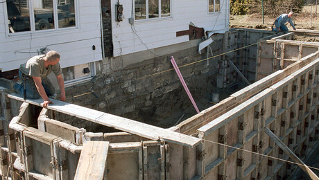
Do you have a photo of what is there now?
First thought is that you can use fewer of the perpendicular beams and the 2x8s can be longer which will simplify and use a lot less hangers and fasteners. The drawback there is that it looks like the length would be just over ten feet creating some waste unless you want to us solid blocking too.
The main beam would be under the perpendicular flush beams. Sizing it is a matter of how much flexibility you would need with the pier locations
Welcome to the
Taunton University of Knowledge FHB Campus at Breaktime.
where ...
Excellence is its own reward!
My height above grade is about two feet. I've attached another JPEG showing that. What I would like to do is put in the main beams, and then joist over top of that putting the next to the house rim joist on and then sliding the whole structure over to within about an inch of the house kind of like the guy in the last issue of FHB did. This may prove too difficult though because of the weight. As you can see my height restriction presents problems when I start adding on all these layers. I was actually refiguring 2 x 10 for the main beams in order to address the issue of them possibly having to carry the roof load from the aforementioned posts that may not be able to sit over top of the deck posts due to the water and gas lines. Does that make sense?
If the posts supporting the roof are anywhere along above the main beam, they can be supported with blocking to the beam. But it sounds like maybe you mean they stand out on the cantilever?Does the gas line run perp to the house or parallel with that main beam?
Welcome to the Taunton University of Knowledge FHB Campus at Breaktime. where ... Excellence is its own reward!
Yes the roof columns would be over the outboard beam not on the cantilevered section. This roof will be near flat with a substantial soffit. The gas and water lines are approx. 8 ft in from the left side as you are facing the house and running perp to the house. There would be some sort of skirting aound the deck so that one would not see the deck posts. Yes the decking will run perp to the house.
I guess my main question here is what would be the best method both structurally and financially to create the deck supporting structure and fulfill both requirements of flexibility for lateral placement of the roof posts independent of where the deck posts need to go, as well as having the joists running parallel to the house so that the decking can go perp to the house. I apologize for my drawings which may be confusing as this was just my first thought as to how to design the deck structure. I'm going to get a photograph of the house as well as create some additional drawings and post them in the next day or two. Thanks for you patience and advice.
A photo with dimensions of existing would be nice.
We use lattice painted dark and flowers or shrubbery around to hide the fact of this sort of cantilevering.I am thinking currently that the best layout would be to have three sections. One about 8'wide in center and two on each end about 12' wide. This moves that pier away from the gas line. If I knew all the dims and pertinent details, I might could design it to eliminate that main beam even.
Welcome to the Taunton University of Knowledge FHB Campus at Breaktime. where ... Excellence is its own reward!
Thanks. I'll be back with more detail.
Sorry about that I forgot to reduce the size of the drawings. Here they are again.
I've attached two j-pegs to try and explain what I need to do. The first is a general outline of the specifics involved. The second shows two options the first being a system of girders running parallele to the house with beams perp to that. I'm just refering to these as girders and beams to keep them straight even though they are are doulbled up beams. The second being just beams running perp to the house. These are just conceptual drawings so bear with me. I've also added a third drawing showing column location. My inspiration for this ganged column design is from the cover of FHB #171 Summer 05 Houses Annual Issue.
I do not have a copy of that issue in front of me so I am simply assuming paired craftsman support columns for the roof. I must also assume without a photo that your front door is centered and that steps leading to it should be in the center position here. What is the size of that door entry and accompanying trim?What I am not understanding so far is why you are trying so hard to keep all the framing dimension layouts nearly equal the latest in increments of 5' and the former in increments of 8'.
Welcome to the Taunton University of Knowledge FHB Campus at Breaktime. where ... Excellence is its own reward!
Won't the decking be running perpendicular to the house, according to the plan? And will the roof columns look a little . . . well, odd, if they're independent of the post locations? Especially with a more open look (vs. a skirt of some type)?
It seems pretty straightforward as drawn.
You've got posts to let your perpendicular beams into, so even with a one foot cantilever if the rim is also let into the posts the only reason to double it is for extra bearing, which can be addressed by blocking.That frees up a little more room to run your roof supports right through the deck onto their own footings wherever you want them.
I'm just starting a good look at this now - see what I see before dinner.
Welcome to the
Taunton University of Knowledge FHB Campus at Breaktime.
where ...
Excellence is its own reward!
Thanks. I'm heading out to coach my Little League Baseball team this evening so I'll check back later. I look forward to your advice and insight.
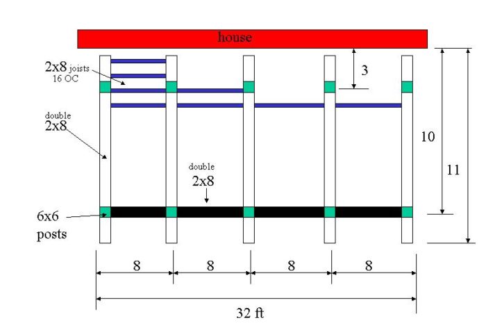
We have dinner due and then taking the grandkids out to see fireworks. Not sure if I'll get back on this tonight.But this view is to show that with the beam sized right, you do not need to worry where piers locate precisely and same with columns to roof. This has the joists in outer sections about 11'8" which works structrually, saves a lot of work and is efficient with materials.Two of the columns are more decorative than load bearing if you use a decent beam above also.
Welcome to the Taunton University of Knowledge FHB Campus at Breaktime. where ... Excellence is its own reward!
Yes this is a centered door. Door and casing are 56" wide. I only had equal spacing as a starting point. I'm all for efficient use of materials as a matter of fact the porch depth could be adjusted to do that as well perhaps using 12' 2x material. The big question was placing that parallel to the house girder such that it spanned the gas line with plenty of room to spare along with constructing it such that the porch columns could be placed anywhere along the length of the girder. In your drawing are the beams that run perp to the house doubled up 2xs with the floor joists hung between those beams? Lastly, what is the best technique for blocking up from the girder at the points where the porch columns would be?
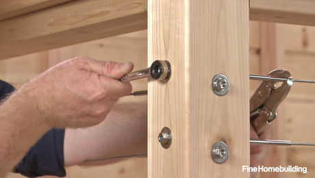
I drew that with 4-2x8 beam for the main one parallel, and doubled 2x8 for the perpendicular beams that the 2x8 floor joists hang from. Almost anything could be used to block up. It depends on the details of your craftsman columns. Could be as simple as a 4x4 running all the way from beam to header beam above before framing the deck joists, then pack out around it with the trim details after doing the deck.Or you could leave the post columns off at start, frame the deck with a couple of joists directly over the beam, and then finish the deck and build the columns up from there.
As a matter of fact, this gets back to the location of piers, if you can locate those piers precisely enough to seat the perpendicular beams on them directly, you can then frame this to not need the main beam at all. It is only there as a convenience, but it does use more material.If I were building it, I would dig top know exactly where that gas line is and where I can p[lace the piers first, before ordering the framing lumber and go from there.
Welcome to the Taunton University of Knowledge FHB Campus at Breaktime. where ... Excellence is its own reward!
Thanks Piffen. You are exactly right that I need to get the locator service out and find the exact location of the pipes so that I can design the piers around that. I figured I would take the build the deck approach and then place the columns on the porch after that. Although, I'm looking at the Chadsworth wrap-around columns to be used with pressure treated as the actual structural post so perhaps the best method would be to run the post all the way from the pier or at least from a direct connection to the girder. What are your thoughts on that?
One thing about the column posts is that they will need to be pretty stout because if I go with the posts at the outer thirds of the porch with a near 20' span in the middle I figure I'm looking at something like a 3.5 x 11 7/8 wolmanized parallam beam to carry the roof load.
"the best method would be to run the post all the way from the pier or at least from a direct connection to the girder. What are your thoughts on that?"It can certainly be done that way but it adds more complications so not the best.To do that - you have to be very precise in how you place the concrete piers, and then you have to support the deck separately from the roof or notch and lag separately into the sides of the 4x4 PT which is not the best way to carry that load. No - I would pier/post up to the carrying beam and then post again above that beam to get up to the roof load."...near 20' span in the middle..."
not sure that I follow...Maybe someone can link to a photo from the magazine that is inspiring this project.
Or
Maybe I need to subscribe to FHB.com
Welcome to the Taunton University of Knowledge FHB Campus at Breaktime. where ... Excellence is its own reward!
This is a link to back issues of the Houses issues. Its a small picture but you can kind of see whats going on with two ganged columns at either end of the porch with a long span in between, essentially leaving the porch with a wide open look. The difference here though is they also have a second story dormer addition coming out over the porch. I'll simply have a low slope to near flat roof only.
http://www.taunton.com/store/pages/fh_toc_171.asp