Take a look at the attached CAD screen snaps.
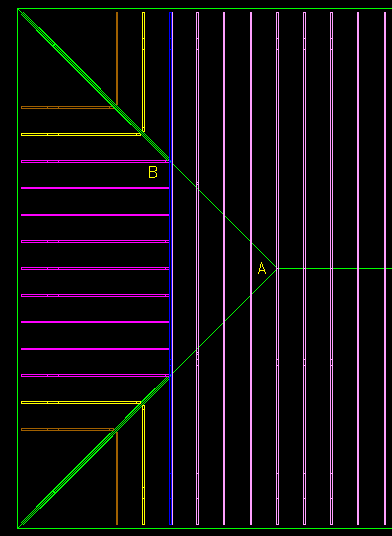
Pic trussplan shows a hip roof. Common trusses come across from right, the last common is at A, then things step down to a two-ply girder. Hip trusses, with hip jacks attached, and monotrusses clipped to the girder, frame out the hipped end.
Everything you see is laid out on 24 centers.
Pic trusszoomA gives a closeup of the last common. Look close and you see that the roof plane intersect is centered on the truss. A minor little piece of chew-off surgery is needed on the peak of the truss, to get the sheathing to plane out.
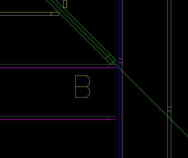
Pic trusszoomB shows how nicely everything comes together at the hip with first adjacent monotruss. An off the shelf Simpson hanger will do just fine here.
I happen to show the hip as doubled to two plies. A one-ply hip would come in just fine, too, but we would use another stock hanger.
My question is this. Am I crazy? My truss engineer is insisting that zoom A is totally wrong, that the truss is to be shifted 3/4-inch right, so that the truss face is in line with the roof plane intersect. He thinks my little nibble is a no-no.
I say, do that shift, and layout across the end comes out wrong.
Who is right here?


Replies
Gene, I agree with the truss guy.
The truss zoom pictures are showing other details that don't be there either. Trust me, the software for residential framing pictures isn't sophisticated to properly show all relevent details. The actual measurements of the trusses will dictate the reality of the component placements.
For instance, look at the doubled hip girder drawing. The zoom shows the second hip as being built differently than the second. In reality, they will simply duplicate the truss twice, or more. It won't be stepped up slightly like the drawing shows.
The truss engineers do not design trusses that need to be cut. Even if they did, I would tip the truss 3/4" out of plumb rather than "snip" the tip. The 3/4" out of plumbness would satisfy most truss design tolerances.
Listen and belive the truss designer....99% of the time they are correct.
blue
Just because you can, doesn't mean you should!
Warning! Be cautious when taking any framing advice from me. There are some in here who think I'm a hackmeister...they might be right! Of course, they might be wrong too!
Take a look at the attached hallucination, Blue.
It is an extension of my other little post, that concerned itself with the hip-ridge-common joint for a stickframe job.
You can see in the bigger dashed boxes, upper left and right, the two truss layouts I am talking about.
As you can see, the truss layout on upper right, preferred by my Quebecois trussie, ends up with a monotruss horribly off center on the end bay.
Not only does this require a second monotruss next to it, but it makes us get all out of whack when doing the roof sheathing.
But, you're right, I should defer to the truss experts!
But, you're right, I should defer to the truss experts!
Gene, I'm sensing some sarcasm.
I'm really not sure of what you are trying to achieve...but I think I'm closing in on your concerns. I'd rather not have to be such a sleuth...I'd rather you just come out and state your intentions.
I think you, and your truss designers are operating with a different set of values. You seem overly concerned about the possibility of a odd span, and the truss designer has some other goal in mind.
Probably 99% of the roofs I frame with trusses have some unequal span in it somewhere. It is rare indeed that all the spans are equal. VEry little weight is given to creating truss systems that don't include spans less than 24", especialy since almost every hip roof that we do has irregular roofs, equal projections and level fascias. As such, I've never given a second thought to attempting to eliminate an unequal span. When I read your post, you are acting as if it is a major concern.
So, with those thoughts in mind, would you please list, in order, your priority list with regards to your roof design. Keep in mind that you have to list everything....projections, pitch, span, fascia, hap, wall height, etc. Maybe, after you make your list, you might notice that you have conflicting criteria. I don't really know..I dont know what your striving for.
I'd accept that truss designers suggestions and add the extra mono jack.
blue Just because you can, doesn't mean you should!
Warning! Be cautious when taking any framing advice from me. There are some in here who think I'm a hackmeister...they might be right! Of course, they might be wrong too!
Blue, you are right about one thing. The doubled girder is best made as two identical trusses, not stepped as shown in my model.
Here is an elevation shot of the wireframe. What you are seeing is how the stepdown trusses are dropped to permit a "laydown sleeper" (my term) truss to spike atop and give us bearings where we need them for our sheathing.
In my stupidity, I modeled the lower of the two-ply girder set to plane out with sheathing and "capture" the bottom end of the sleeper.
Silly me! That's just asking for a problem. Each new cut scheme and setup, at a truss plant, introduces a new possibility of a screwup. We'll make them both the same, like the one on the right.
But the other thing, your supposition that I am using some kind of software for residential framing, is incorrect. I modeled this whole thing myself from scratch. The computer isn't doing anything I don't tell it to do.
I use this process to "build it in my head," and think everything through before I get started. Doing the whole truss thing in 3D took me six hours.
The pdf attachment shows a rendering of most of the low roof portion of this project.
Gene,
This is our typical detail for the girder/purlin for a "dropped" hip. The girder plies are determined by how far the setback is and/or what it has to carry.
In my stupidity, I modeled the lower of the two-ply girder set to plane out with sheathing and "capture" the bottom end of the sleeper.
Silly me!
It's not silly. If you want that type of positive support, they simply can move the entire girder setup 1 1/2" toward the center of the house and still make the two girders the same. I've never seen it done, but it's possible. It would require an adjustment to the mono jacks, but all in all, this just complicates a simple girder.
All our hipsets are dropped to allow for a 1 1/2" "furring". On the last three houses, they sent out the layon prebuilt. On the previous 100 sets, we did the layon our selves with 2x 4. The first few hipsets that I ever did back in the early 80's, they didn't drop the trusses....we had to individually block in between each truss. I actually took it upon myself to move the system inward and create roof for a layon on one job....sometime after that, they automatically designed them to add the layon.
blueJust because you can, doesn't mean you should!
Warning! Be cautious when taking any framing advice from me. There are some in here who think I'm a hackmeister...they might be right! Of course, they might be wrong too!
Blue, I'm sorry I seemed flippant in my remarks.
Let me try to say what my goals are in thinking this through.
1. Make the manufacture of the trusses simple by minimizing the number of different trusses.
Blue, I'm sorry I seemed flippant in remarks in earlier posts.
I really want to defer to the guys who know much more about truss design, layout, and installation, than I. Like the truss engineers. And guys who frame with trusses routinely. They have all been there and done that.
I am just a guy doodling in 3D CAD, trying to think my way through it.
The reason I like to model it in 3D CAD, is because it helps me in two important ways.
One, if my CAD model represents the actual truss shapes, at the actual layout positions we'll use at job time, I can use my model to check the drawings I get from the trussie, and correct any errors that might be there.
Two, the model helps me get all the bearing walls built spot-on, and to pre-plan any details I need ahead of time. Like, for example, extra studpacks under heavily loaded girders.
So, here are my goals in doing this exercise.
Minimize my truss package cost.
Reduce truss counts. Arrange the layout at hip end so that extra montrusses aren't required.
Reduce truss types. Make all two-ply trusses identical. Do all hip jacks so they are "handshake" mirrors of one another.
Minimize my erection cost.
Simplify layout by eliminating any odd bays off layout. Reduce sheathing cuts by making all centers fall on layout.
Buy lay-on trusses for hip dropdown areas that drop into place without fail.
_________
I've done five trussed-roof structures since I quit my desk job and took up housebuilding, and of the five, I have CAD-proofed the truss design of four this way. Every one of those that were CAD-proofed have gone together quickly and easily.
The one I did not do, but left up to the truss company, had problems. I screwed myself on time, and got too busy, with no time left, and said OK to the order.
We ended up pitching some big ones off the roof, and then I chainsawed them up for the burn pile, after ordering corrections and paying for extra framing labor, crane time, and materials.
The first one I ever did, the trussie got things so messed up, at submittal time, I ended up taking my laptop to his office, and we worked from 4 pm until almost 11 one night, going through everything, getting his model to match mine.
So, back to the job at hand.
The attached pic shows one of the "segments" of the low roof of the house to be built.
The monotrusses M4 and M5 can be seen marching into valleys, where they will detail out with the kind of valley cuts and valley pieces you advised me about in posts from back before Christmas. I figured that going into valleys like this, there is nothing about the valley locations that determine layout.
So I figured, mathematically, everything can begin with point A, the place on the map where the hipped roof plane intersects the ridge. I thought that all sheathing can run on perfect 24 centers except for the "wild" cutting we have to do at hips and valleys.
It looks to me that any roof like this, a U-shaped roofplane group wrapping a hipped end, lays out most economically by locating a common truss at point A, and working both ways from there. It doesn't matter whether the building width (the vertical length in my plan) is 36'-0" or 36'-3 7/16", or any figure. A monotruss will hang off the girder at dead center, and the layout will be 2/0 both ways, out to the "wild" last jack on the hip adjacent the corner.
So, I'm still left with my 3/4" question. Is the common centered on the point, or offset to its hip-side edge?
I'll take my CAD model, plus questions, to my trussie in the a.m. Let's see what happens.
Edited 2/21/2005 11:05 pm ET by Gene Davis
Okay Gene, I know your serious now.
Heres a very rough diagram of how we often get our hip sets sent out. I'm trying to show you that the tops of th mono trusses extend higher than the hip set. The tops of the monos then plane with the layed on 2x4.
Over the years, I often wondered why the monos never were layed out exactly 24 oc. They were always short by 1 1/2". Basically the measurement shown on my girder would be 6' if it had a perfect 24" layout, but it never is. It is short because they are subtracting one half the thickness of the common rafter on each side.
Hey! I think I just discovered your "problem". Your first pictures showed a ridge, but trusses don't use a ridge.
Now...since I'm rambling all over...lets discuss some of your criteria. You seem hell bent on eliminating the cuts of the plywood. You'll have to design both sides of the house to exactly 24" modular layout to eliminate all ply cuts.
blueJust because you can, doesn't mean you should!
Warning! Be cautious when taking any framing advice from me. There are some in here who think I'm a hackmeister...they might be right! Of course, they might be wrong too!
Hey, Blue. How ya doin.
("How you doin" comes from reading too many Elmore Leonard novels, one of which I finished late last night. Best writer of mystery novels I know of. Lives in Detroit.)
Let's unravel this truss thing.
Go back and look at my sketch called "stupidity" in post #5 of this thread. It is a wireframe elevation shot of the two-ply girder, showing the drop for the sleeper, and monotrusses and hip trusses clipping to it from the left.
I was first using it to show you how I had inefficiently designed the hip-side of the two-ply to be different from the ridge side. We'll change that so that both plies are made the same, like the one on the left in the pic.
The monotrusses on the hip side plane out, and will thus have their top end tips sticking up above the girder, as is shown in the view.
And my other thread about hip-ridge? I know that relates to stick framing, and not to trusses. I was asking that to see what the stickframe guys, who are perfectionists, would say about layout across the hip end.
But back to the question.
My layout yields a hip set with 9 identical monotrusses, two identical hip trusses, and two sets of 4 each identical jack trusses. It is the least number of part counts and setups on the truss press table. Efficient.
Sheathing across the hip end has its 2/0 layout working both ways from the center, and the only sheathing cuts are at the hips. Efficient.
From anywhere in the middle of the sheathing runs going from hip down to valleys, on my U-shaped plan, you can pop a full sheet on, and work both ways from there, and once again, the only sheathing cuts will be at hips and valley conditions. Efficient.
The only beef my trussie has is the little nip we make at the common peak at point A, to make things plane out. In actuality, with this 4.5 pitch, and 5/8 sheathing, we'll not nip it at all, because we'll be leaving sheathing short of the ridge, for our breathing hole.
For your viewing pleasure, I have attached a pic of a part of the first truss job I ever did with this CAD-proofing method. One hipped end, and on the underside, a hipped ceiling over one area, a scissors vault over another, and a tray over a third. Erected using a crane near Angola, Indiana, not far from you.
Gene, I'm not sure that you are right about that nip.
Instead of showing the closeup view with a ridge, show it with the trusses and then the layed on 1 1/2" framing members that will butt it.
blueJust because you can, doesn't mean you should!
Warning! Be cautious when taking any framing advice from me. There are some in here who think I'm a hackmeister...they might be right! Of course, they might be wrong too!
Blue, take a look at the screen caps attached.
"SleeperRidgeLine" was taken with only the CAD level with sleeper truss shown. It is a straight down plan view. I use an arrow to point out the edge of the truss chord that lines to the ridge line where roof planes intersect.
Note that the top of the sleeper is whacked. That is the truss plant's job.
Take a look now at "SleeperWTrusses." The CAD level with the trusses is now turned on, as well as the one with the roof plane lines.
I am pointing out where the little field nip is done to the peak of the common truss, whose centerline runs through the peak point. I can probably do it with my trusty rasp, or my knife.
But, as I said, I might not do the nip at all!
The last screen cap pic shows the wireframe model in elevation, and I use an arrow to show the nip location. You can see that sleeper truss laying in there quite nicely, with its top surface being the hip roof plane.
Milkbone?
Okay Gene, now I know you're having some theoretical fun.
Long ago, I stopped fretting about things like that. Like I said earlier in this thread, I'd probably just push the truss out of plumb the 3/4". I do that on every job without nary a thought. I set a nail at the peak, string a line from the corner of the eave and tip of the peak, and try to move the truss to perfectly align over the tip of the hip girder. I do this because I'm typically trying to create a straight hip that is governed by two fixed points...the fascia and the girder.
I really wouldn't be nipping that tip, because I'm simply moving it. If it was leaning in too much, more than I could lean it, I'd simply cut it. On some jobs, I've had to nip it, some I chip with my hammer, others had to be whacked down 12" and an engineered repair done. In any three of the events that I just offered, my entire thought process woult total less than 30 seconds, on average. The only reason that I'm allocating the 30 seconds is because I'll somewhat more carefully explore my options before whacking 12" off the top, but once I make that decsion, it only takes me five more seconds...
You are making a mountain out of a molehill and you may very well be correct, but I reserve my judgment until you give me all the numbers. I can then very easily calculate the exact theortetical point. I'm not willing to accept the CAD drawings as proof...I only work with numbers and reality.
blueJust because you can, doesn't mean you should!
Warning! Be cautious when taking any framing advice from me. There are some in here who think I'm a hackmeister...they might be right! Of course, they might be wrong too!
Blue, I love nit-pickin', and making mountains out of molehills. I can't help myself. It's the engineer in me.
Just as you enjoy table boogerin' those wall assemblies, and watching them fly up and away, then come down and go snick-snick right into place, I like to do the same with a roof assembly. Actually, any kind of assembly, although roofs are the most fun.
I had the opportunity to precut a stick framed roof once. Did it as an exercise, just to prove to myself I could. Hips, dormers, valleys, funky rafter tails, etc. Right from the prints, and began cutting as soon as the lines got snapped on the decks to proof out the plan.
I have finished swapping prints and phone calls with the truss engineer, and am happy to say he is doing the trusses per my layout, and all the parts are matching dimensions I can pull from my CAD model.
The precast concrete foundation under this thing is all pre-engineered, too. The CAD designer just made her submittal to me of assembly, erection, and all shop part prints, and whaddya know, all dimensions match up to my CAD model, too.
Now, if I can only get the framing part in between right!
That should be a piece of cake Gene.
If I was the truss guy, I would have accepted your cad drawing measurements without an argument. I cannot imagine gaining anything by fighting you about 3/4"!
blueJust because you can, doesn't mean you should!
Warning! Be cautious when taking any framing advice from me. There are some in here who think I'm a hackmeister...they might be right! Of course, they might be wrong too!
So - How long ya got? I could talk about this for a loooooooooonnnnnnngggg time.
Keep in mind that there are as many different ways of doing hip systems as there are truss companies. Even within a company, different designers do hip systems different ways. And everyone seems to thnk their way of doing it is right.
But to address your first question - Is the first peaked truss to the RIGHT of the intersection of the ridge lines, or centered on it? That depends on who designs the hip end.
Take an example of a 32' hip system. Let's say a company would use a 7' 11 1/4" setback. (The distance from the end of the building to the FACE of the girder)
That would mean the girder has a 16' 1 1/2" flat top. The advantage to this situation is that the end jacks are all exactly 2' O.C. across the end of the building.
In this case, the first peaked truss would be CENTERED on the intersection of the ridge lines, as shown in your "trusszooma" drawing.
Go down the road to the next truss company, and they'll use an 8' 0" setback. This saves lumber, as the hip girder has a 16' 0" flat top. But the jacks on the end have on odd space in them, meaning the plywood has to be cut somewhere.
In this case, the first peaked truss would be to the RIGHT of the intersection of the ridge lines.
.
If you've had problems with hip systems, I'd suggest trying a different approach. Rather than spending 6 hours trying to model a hip system when you don't know how they're done, have the truss company do it. Tell them they have the order, but ONLY if they'll give you a layout and shop drawings to approve BEFORE they're released for fabrication.
I could lay out and design a 32' hip system and print out drawings in less than half an hour. (without interruptions) And I dang well know how to keep as many trusses as possible the same in order to reduce costs.
I've told them they have the order. I'm asking for a full set of drawings for my review and signoff, before fabrication.
You have helped greatly in clearing this question for me. Thanks!