So here’s the rest of the story…
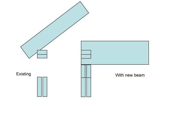
I’m removing a load bearing wall. This one used to be an exterior wall prior to an addition to the house. To remove it, I’ve got to run a 3-1/2 x 11-7/8 LVL across a 14′ span. One end will tie into a concrete block wall and I think that should be straight forward.
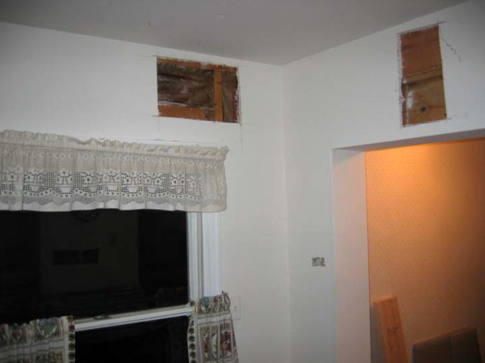
The other end ties into an exterior wall, 2×4 studs. To maintain ceiling height with the adjacent room, the new beam will be lowered 5″. The beam will rest on a new header over an existing window. As I’m looking at this more and more, I’m perplexed. The new header will divide the wall top plate. I presume that I shouldn’t cut the top plate and instead should notch the beam so it fits around the top plate. Is that right?
I’ve attached a photo of the room which shows the exposed framing (look at the LEFT hole in the drywall) and a drawing of what I think I should do. The rafter is shown just for reference and shouldn’t be an issue because I think the new beam will be located between rafters.
Appreciate any and all ideas.


Replies
Ken
What loads will the LVL be taking?
Is there any reason you can't park the LVL straight onto the top plate ( truncate the top corner where it meets the roof) and then frame down to your ceiling height?
Be aware that if the LVL is loadbearing and you are now transferring half the load to the block wall and the other half to the new header you have to look carefully at your new header size along with the transfer of loadbearing points ( floor/ joists/ blocking issues )
regards
Mark
http://www.quittintime.com
Mark, I guess i could do that. Hmm, will have to think that through some more. how will header size come into play? I was thinking that I'd just cut a header so it rested on top of the existing. Most of the load will go on the concrete block side.The wall I'm removing is the outside wall to a bump out to the original house. That's why it's actually in line with the window on the addition.
I'm getting more scared here. How can you say that MOST of the load the beam carries will be transferred back to the cmu wall? did you come up with a new way to make gravity work heavier in one direction than another?Also - as I see from your photos, if I understand you right, the wall that has an openning in it is the one you plan to remove. The openning goes into the addition and in removing that wall, you will remove the portion of it to the left of that openning as it abbutts the wall with the window in it. That portion of wall might very well be action as a shear brace for that corner of the house. if so, the end of the beam that connects the cmu wall will need to have fastening to compnsate for the lost shear strength, and the cmu wall will need to be strong enough also. In other words, if the wall junctioned in the photo wants to lean out away from the beam after this is don, it will be acting to pull the opposite end of that beam away from the cmu wall. In doing so, it is opossible that only the bond of the mortar is all that prevent s the cmu wall from being destroyed.
Welcome to the Taunton University of Knowledge FHB Campus at Breaktime. where ... Excellence is its own reward!
If I do what you're saying, put the beam on top of the top plate, do I need to reinforce the top plate since it's probably only 2- 2x4s and the studs are probably 4-6" away from the beam?
Ken
The bottom line is support support support. As Boss Hog said. Point loads. Wherever your beams end, they need support ( whether the LVL or header). The top plate takes no load in a case like this. Just consider it decorative.
So in answer to your question. Yes you need a window header large enough to take the new loads you are puttting onto it. Re your comment earlier that the block wall will be taking mopst of the load, you may like to explain a bit more?
regards
Markhttp://www.quittintime.com
How did you end up with an "existing" window at the end of an old bearing wall?
Something sounds odd here...
"I presume that I shouldn't cut the top plate and instead should notch the beam so it fits around the top plate. "
Absolutely not. Cut the plates out - Don't notch the beam.
Also - You need to take a look at your window header. It appears that you're adding a point load above it.
About the point load, yes, I think am. Are you suggesting that I change the framing around the window so the header rests on a stud (king stud, is it)? Sounds like what Mark was alluding to.
I was thinking more that the header may be inadequate if the loads on it are changed.
Somewhere, over the rainbow... That's where the airline sent my luggage.
You are scaring me son.
The window header must be sized to handle your load - half the weight you are planning for the lvl to accept. I don't know how much that is, but I assume a roof only because of the size and span of the lvl
The jacks and king stud should also be studied to foundation.
Neither beam nor top plates should be notched. You should have a Simpson hanger sized for the load and fastened as recommended.
and for the worst of your offenses - you assume that the end on the cmu wall is a no brainer. What kind of block wall is this? Structrual or not? What sort of foundation does it sit on? is it stabilized well enough for the load? Should steel and core filling be considered at the end under the load? Ooops, is this resting on an end of said wall or does it coneect operpendicular to the cmu wall?
Welcome to the
Taunton University of Knowledge FHB Campus at Breaktime.
where ...
Excellence is its own reward!
The BT Gods are taking mercy on me and thank goodness. The light shines brighter...
Will reframe the window wall for the header as you say to do and will also check the rafter framing tonite to make sure that I can put the beam above the top plate. How can I figure out how big of a header that I need? This will support the tail ends of rafters.
As for the support to the ground, the CMU was originally an exterior wall with a foundation. That should be sound enough, right? I think that this beam will now rest atop that CMU wall, but will have to check it. It'll essentially be an extension of the existing CMU wall.
Am I still scaring you?
not trying to beat you up. Let's find the humour and the solution - but you have a complex situation because of the addition already done. Loads have been added and transferred that qwew have no idea about because we are working in the blind. So far we only know a third of what we need to know. Your Q has been answered re the one connection but not the overall situation. let's go back to the beginning. how did you determine that this particular size of lvl would do the job? My impression is that it will handle a normal load for that span in an area with low snow loads, but at some paoint an addition was made which might have ( probably did) added more load to that wall you plan to remove. Without studying the whole strcture as it exists and knowing what lands where, it would be impossible to give good advice. I really think you need an engineer or a framinig carp with good engineering skills.For instance, the fact that the window header is only 2x6 on an exterior wall is minimalist to me and suggest that other minimalist technuiques may have been employed in the past. This means that we can assume nothing. Those techniques may have been fine in the original plan and with the original codes. But after how mnany changes now? A house of cards stands fine at first, but you can't take too many chances with changing it.
Welcome to the Taunton University of Knowledge FHB Campus at Breaktime. where ... Excellence is its own reward!
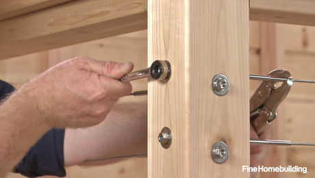
Ken, listen carefully to what the smart people are saying. I also recommend you take a look at the tji website for spec and engineering of lvl beams. They make them and test them so you don't have to. They have illustrations, span specs, and even built up beam nailing specs (ie: number of rows, size of nails, and spacing of nails). They have attachment illustrations for your situation also. Just to provoke more thought, I'll try to attach (first try ever) a photo of a similar job I did. NOTE: ATTENTION: The photo does address shear walls attachment!!!
Kevin
WOW! That picture came out way too big. 2nd try. BTW, just noticed that pic was taken prior to 90 degree simpson ties being installed connecting the lvl to both top plates, please picture it there.
Kevin
I should have said in the original post that I did some homework on this one. Appreciate the ideas on the details.Consulted an engineer for the beam sizing.Attached is a pic of the room and you can see the bumpout and the wall that I'm removing. Looking closer at the framing in the attic, I think I'll cut back the roof sheathing from the old part of the house to expose the rafter and joist ends. There isn't any rim joist, so I'll raise this beam into the ceiling and place it there, using joist hangers where I can and toenailing where I can't. I'll nail into the adjacent trusses in the new addition as much as I can. They run parallel to the new beam. The new beam will rest atop the CMU cap plate. I'll talk to the guys at the lumber yard tomorrow about the right Simpson connector to tie in.Still working on header sizing......and still dumb, but not stupid (as far as I can tell, haha)
Edited 4/1/2005 10:46 pm ET by ken
oops, here's the photo of the room...
The new beam will rest atop the CMU cap plate.
What is a CMU cap plate ?
Aren't we talking about the beam being installed in a wood framed attic ( no CMU here, just in the basement ) ???
carpenter in transition
Thanks a lot for the "constructive" (yuk yuk) criticism! It really helps me out.
I've got two LVL beams going in. I've been talking about thus far about a beam which will extend across the top of an existing CMU wall. This beam will support the ends of ceiling joists and rafters, using hanger joists. The opposite end will rest atop the cap plate (supported by header). To attach it to the CMU, building supply guys suggested using a hanger joist, mounted upside down with screws into the concrete. Hmmmm
An alternative would be to use two MGT Girder tiedowns, bolted to the concrete, and straddling the doubled up LVL.
The other end of that beam sits atop framing and I was thinking of using MTSM strap ties, nailing to the beam and to the cap plate and the header.
As for the other LVL beam that I'm putting in, one end will sit in a joist hangar and the other end sits atop and perpendicular to a CMU wall. Again, was thinking of using the MGT Girder tiedowns, straddling the beam. An alternative to the MGT tiedowns would be a simpler FA8 foundation anchor, bolted into the CMU and nailed to the beam. This beam, by the way, will be supporting rafters at birdsmouth, reinforced with hurricane ties.
Am I still scaring you or am I on the right track here?
I want you to get back to that engineer right now.I cannot fathom any engineer sizing this beam and not specifying methods of attachment. As it stands right now, I think we know more about this situation than he did when he sized it.
Welcome to the Taunton University of Knowledge FHB Campus at Breaktime. where ... Excellence is its own reward!
Piffin, Thanks for that suggestion. As I've said before, I get smarter with reading nearly every opinion. As a DIY guy, it's good to hear from the pros, here, in the building supply, and of course the PE.Anyone have any "constructive" thoughts, though?
I like to think that inserting it so it will stay there, do the job you intend it to do, without hurting the structure that exists now, or yourself, IS a pretty constructive thing to do. All this mish mash of opinions from everyone from truck driver, hardware salesman, and internet columnist to painterr, dog cathcer, and mother in law is niot the way to get this right.
Welcome to the Taunton University of Knowledge FHB Campus at Breaktime. where ... Excellence is its own reward!