FHB Logo Facebook LinkedIn Email Pinterest Twitter Instagram Plus Icon Close Icon Navigation Search Icon Navigation Search Icon Arrow Down Icon Video Guide Icon Article Guide Icon Modal Close Icon Guide Search Icon Skip to content
Subscribe
SUBSCRIBE TODAY

Save up to

set_percent% off

the cover price

In-depth articles, up-close photography, and detailed illustrations in every issue.

Subscribe Now!
Subscribe
  • How-To
  • Design
  • Tools & Materials
  • Videos
  • Blogs
  • Forum
  • Magazine
  • Members
  • FHB House
  • Podcast
  • Join
  • Log In
Subscribe

Fine Homebuilding Project Guides

Wiring

Guide Home
Chapter
  • Working with Electricity
  • Tools and Materials
  • Receptacles and Switches
  • Lights and Fans
  • Rough-In
  • Outdoor Wiring
  • Panels and Subpanels
How-To

Wiring a Switch Loop

Learn the code-compliant method for wiring a switch when an outlet or fixture box is closer to the power source than to the switch box—plus see the way it was commonly done in the past.

By Mike Litchfield, Michael McAlister

There are two ways of wiring a switch loop. The old-school way, shown in the first drawing below, can probably be found in 90 percent of homes but has been superseded by changes in the electrical code. The second way, shown in the second drawing below, conforms to the NEC requirements and should be used for new installations, particularly if you want modern devices on any given circuit to work properly.

The historical method

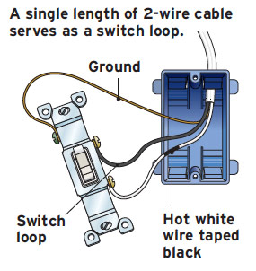
Before the code changed, it was common to run a single length of 12/2 or 14/2 cable as a switch loop. This means bringing the power down from the fixture to and through the switch and then back up to the fixture. As such, the white wire taped black in the 12/2 or 14/2 switch loop functions as the incoming hot wire, and the black wire acts as a switch leg to return the power to the fixture. Here, the white wire is actually a hot wire and is taped black to identify it as such.

Turn off the power and test to be sure. At the outlet or fixture box, splice all the grounds together. Attach the source neutral wire to the fixture neutral wire. Attach the source hot wire to the white wire (taped black) of the switch loop. Last, connect the switch loop black wire to the black fixture wire.

Note: Here, for convenience, we bend the rule of using a white wire only as a neutral wire and instead wind black tape on each end of the white wire to show that—in this case—the white wire is being used as a hot wire.

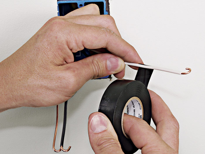
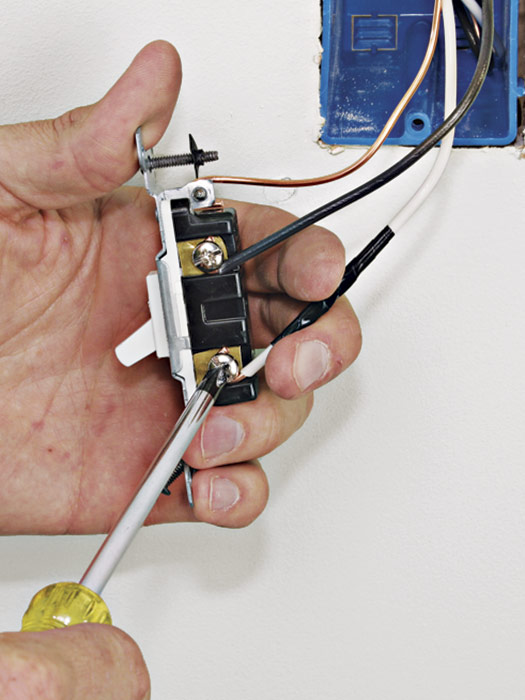
At the switch, start by stripping and looping the wire ends. Next, tape the white wire with black electrician’s tape to indicate that it is serving as a hot wire to the back-fed switch 1. The NEC dictates that the white wire in back-fed wiring is always the hot lead (power coming in). The black wire, on the other hand, is the switch leg that runs back to the fixture.

1 In this historical method, tape the white wire black to show it is a hot wire.
1) In this historical method, tape the white wire black to show it is a hot wire.

As is customary, connect the ground wire first.
2) As is customary, connect the ground wire first.

Connect the switch leg (black wire).
3) Connect the switch leg (black wire).

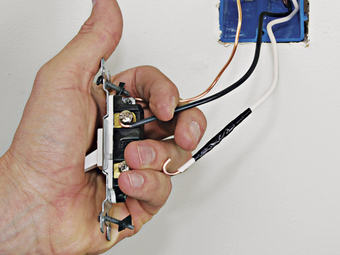
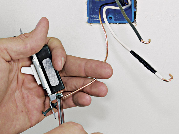
First, connect the ground wire to the green ground screw 2 on the back-fed switch. Next, connect the switch-leg wire (black) 3, then the hot wire (white taped black) to the switch terminals 4. To keep looped wire ends snug against the screw shaft as you tighten down the screw, pull gently on wires, as shown. Not fumbling with wire ends saves time.

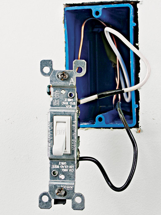
Finally, tuck the wires into the box 5, screw the switch to the box, and install the cover plate.
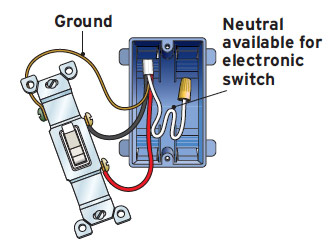
Connect the hot lead wire to the fixture last.
4) Connect the hot lead wire to the fixture last.

tuck in wires and screw the switch to the box
5) When all connections are tight, tuck in wires and screw the switch to the box.


Wiring a Switch Loop: The Historical Method

Wiring a Switch Loop: The Historical Method

In the “old school” way of wiring a switch loop, a single length of 2-wire cable serves as a switch loop. The white wire in the cable is taped black to show that it is being used as a hot wire. This method was a good solution because it conserved copper and was quick to wire, but it has been superseded by the method shown above to facilitate the needs of some common types of electronic devices.


The modern method

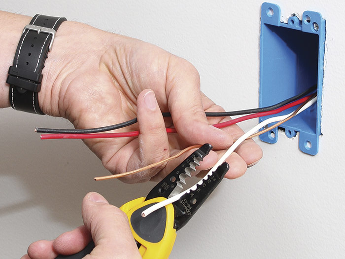
This method of wiring a switch loop reflects recent code changes. Specifically, the NEC requires that there be a neutral in every switch box because some electronic timer switches and other energy-saving controls need a neutral. So if you want to use a switch-loop approach, you must use three-conductor (3-wire) cable. The neutral of the 3-wire cable must be connected to the neutral of the circuit, even if the neutral is not going to be used.

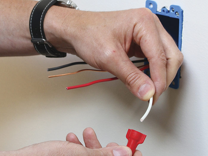
This installation sequence is done with the power off. From the power source at the fixture, run a length of three-wire cable to the switch box. Remove cable sheathing 1 and strip 3⁄4 in. of insulation from the ends of insulated wires. If the switch doesn’t need a neutral wire, cap the neutral wire 2 and fold it into the switch box.

With power off, strip sheathing from the 3-wire cable that runs from fixture box.
1) With power off, strip sheathing from the 3-wire cable that runs from fixture box.

neutral wire
2) If the switch does not need a neutral wire, cap it and fold it into box.

First attach the ground wire to the switch.
3) First attach the ground wire to the switch.

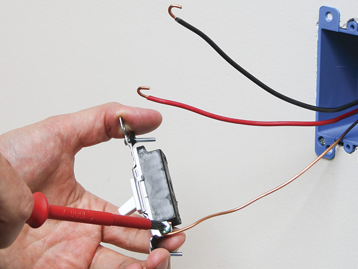
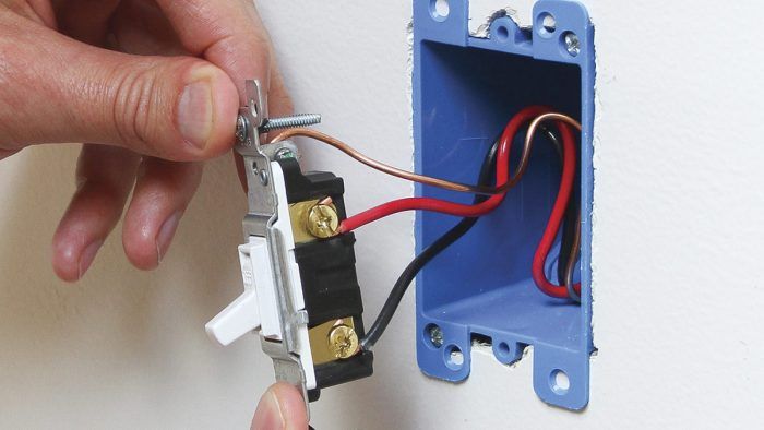
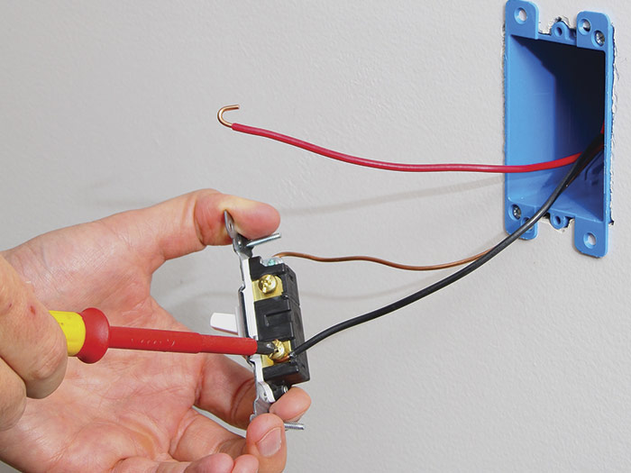
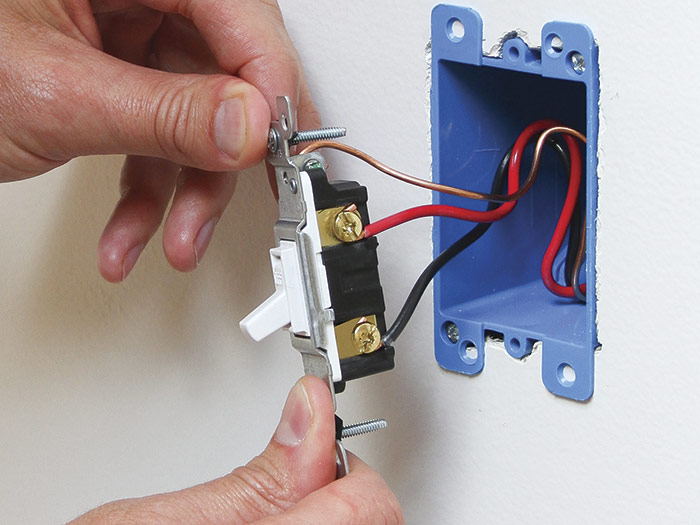
If you are attaching switch wires to screw terminals, loop the wire ends. Connect the ground wire to the green ground screw 3 on the switch. Next, connect the switch-leg wire (red), and the hot lead (black), which runs back to the fixture 4. Keep looped wire ends snug against the screws as you tighten them down. When all wires are secured, gently fold them into the box 5, screw the switch to the box, and install the cover plate.

4  Attach the switch leg and the hot lead.
4) Attach the switch leg and the hot lead.

Fold the wired device into the box and secure it with mounting screws. Replace the cover plate.
5) Fold the wired device into the box and secure it with mounting screws. Replace the cover plate.


Wiring a Switch Loop: The Modern MethodWiring a Switch Loop: The Modern Method

The NEC requires that there be a neutral in every switch box because some electronic timer switches and other energy-saving controls need a neutral. Thus, if you want to use a switch-loop approach, you must use three-conductor (3-wire) cable, connect the neutral at the power source, and then cap off the neutral in the switch box. Because 3-wire cable has both a black and red conductor, there is no need to re-identify the white conductor as hot, as was done in the old method, because the white wire is a neutral.


Wiring Complete, 3rd Edition

Excerpted from Wiring Complete, 3rd Edition (The Taunton Press, 2017) by Michael Litchfield and Michael McAlister

Available in the Taunton Store and at Amazon.com.

Sign up for eletters today and get the latest how-to from Fine Homebuilding, plus special offers.

Sign Up
Previous: Replacing a Single-Pole Switch Next: Wiring a Linear Slide Dimmer

Guide

Wiring

Chapter

Receptacles and Switches

Log in or create an account to post a comment.

Sign up Log in

Become a member and get full access to FineHomebuilding.com

Wiring

Wiring

Trusted, code-compliant guidance from the pros for working safely on any wiring project

View Project Guide

View All Project Guides »

Become a member and get unlimited site access, including the Wiring Project Guide.

Start Free Trial

Working with Electricity
  • Basics
  • Safety
  • Troubleshooting and Upgrades
Tools and Materials
  • Electrical Tools
  • Electrical Boxes
  • Cables and Wires
Receptacles and Switches
  • Materials
  • Wiring Receptacles
  • Wiring Switches
Lights and Fans
  • Lighting Design
  • Installing Lights
  • Fans
Rough-In
  • Planning
  • Installing Electrical Boxes
  • Running Cable
  • Retrofit Work
  • Making Connections in Boxes
  • Electrical Conduit
Outdoor Wiring
  • Basics
  • Outlets
  • Installing Lighting
Panels and Subpanels
  • Understanding Panels
  • Circuits
  • Installing a Subpanel

Fine Homebuilding

Follow

  • twitter
  • facebook
  • instagram
  • pinterest

Newsletter

Get home building tips, offers, and expert advice in your inbox

Sign Up
This site is protected by reCAPTCHA and the Google Privacy Policy and Terms of Service apply.
See all newsletters

Membership & Magazine

  • Online Archive
  • Start Free Trial
  • Magazine Subscription
  • Magazine Renewal
  • Gift a Subscription
  • Customer Support
  • Privacy Preferences

Taunton Network

  • Green Building Advisor
  • Fine Woodworking
  • Fine Gardening
  • Threads
  • About
  • Contact
  • Advertise
  • Careers
  • Copyright
  • Terms of Use
  • Site Map
  • Do not sell my information
  • Privacy Policy
  • Accessibility
  • California Privacy Rights

© 2022 The Taunton Press, Inc. All rights reserved.

X
X
This is a dialog window which overlays the main content of the page. The modal window is a 'site map' of the most critical areas of the site. Pressing the Escape (ESC) button will close the modal and bring you back to where you were on the page.

Main Menu

  • How-To
  • Design
  • Tools & Materials
  • Video
  • Blogs
  • Forum
  • Reader Projects
  • Magazine
  • Members
  • FHB House

Podcasts

  • FHB Podcast
  • ProTalk

Webinars

  • Upcoming and On-Demand

Account

  • Log In
  • Join

Podcasts

  • FHB Podcast
  • ProTalk

Webinars

  • Upcoming and On-Demand

Popular Topics

  • Kitchens
  • Business
  • Bedrooms
  • Roofs
  • Architecture and Design
  • Green Building
  • Decks
  • Framing
  • Safety
  • Remodeling
  • Bathrooms
  • Windows
  • Tilework
  • Ceilings
  • HVAC

Magazine

  • Current Issue
  • Past Issues
  • Magazine Index
  • Subscribe
  • Online Archive
  • Author Guidelines

All Access

  • Member Home
  • Start Free Trial
  • Gift Membership

Shop the Store

  • Books
  • DVDs
  • Taunton Workshops

More

  • FHB Ambassadors
  • Reader Projects
  • Podcast
  • Customer Support

Account

  • Log In
  • Join

Newsletter

Get home building tips, offers, and expert advice in your inbox

Sign Up See all newsletters

Follow

  • twitter
  • facebook
  • instagram
  • pinterest

Join All Access

Become a member and get instant access to thousands of videos, how-tos, tool reviews, and design features.

Start Your Free Trial

Subscribe

FHB Magazine

Start your subscription today and save up to set_percent%

Subscribe

We hope you’ve enjoyed your free articles. To keep reading, become a member today.

Get complete site access to expert advice, how-to videos, Code Check, and more, plus the print magazine.

Start your FREE trial

Already a member? Log in