
Floor Framing Starts with the Mudsills
If you want to get the first-floor platform right, squaring and leveling the mudsills is a critical first step.
The most important part of a house frame is the first-floor deck: the mudsills, the beams that support the floor framing, and the floor frame itself, including the joists and sheathing. If you want the rest of the house to be level, square, and plumb, you’d better start with a square and level platform.
Before getting started, look over whatever plan shows the floor-framing details; they might be on the first-floor framing plan or, as in this case, on the foundation plan (see “First-Floor Framing Plan”). Make note of any special details, such as openings for stairs and chimneys, and look for areas marked for extra framing needed to carry heavy loads, such as large bath tubs. Pay particular attention to locations where the joists change direction or cantilever over the foundation walls to support a bay window or balcony. These areas are easy to overlook as framing progresses and, believe me, you’ll want to get them right the first time. Use a highlighter to flag these features so you’ll be sure to pay attention to them as framing progresses.

LEFT SIDE
BACK OF HOUSE
RIGHT SIDE
FRONT OF HOUSE
Bulkhead
Rear joists
Support beam
Stair chase
Front joists
Lally columns
Over the years, I’ve been lucky to have worked for builders who were meticulous about getting the first-floor deck right, but I also spent a short time on a crew where speed trumped accuracy. Walls on the shoddy first-floor deck seemed to go up easily…until we tried to straighten and square the second floor. Walls had to be set out of plumb or off the layout to compensate for discrepancies in the first-floor deck. At the roof, the rafters didn’t meet the ridge squarely, and with the framing out of whack, every piece of fascia had to be custom cut to fit. Trimming out soffits and returns that weren’t square was an even bigger headache.
My advice: Take your time and get the first-floor framing as close to perfect as you can. Otherwise, you’ll have to spend extra time and money to fix problems later. Get this part right, and the house will be better for your efforts.
Mudsills
Mudsills (also known as sills or sill plates) are made of rot-resistant, pressure-treated wood and are bolted to the top of the foundation. Historically, however, mudsills literally sat in the dirt below the house. If you want to get floor framing right, squaring and leveling the mudsills is a critical first step.
Check the foundation
The first step is to measure the foundation and give it a quick check for square. Don’t assume that your foundation contractor got it right, because even the best have bad days. To check a foundation for square, have two crew members stretch a 100-ft. tape diagonally from one corner to another, as shown in the photo above. Note the measurement and repeat the process at the other two corners. The numbers don’t have to match exactly but they should be less than 1 in. apart. If the difference is greater, you can sometimes compensate by installing a wider mudsill and letting it hang over the foundation slightly, but this arrangement is hardly ideal.

Taking Long MeasurementsTo take long measurements, such as the diagonals used to square a foundation, one crew member holds the end of the tape while another crew member reads the measurement. Because it’s difficult to hold the hook of the tape at a specific point, the person on the “dummy end” usually holds the tape at a given mark such as 1 in. The person at the other end then subtracts that inch from the overall measurement, a procedure called burning an inch. But many carpenters burn a foot instead because subtracting a foot is easier. Either way, the person holding the end of the tape should call out the number he’s holding (“Burning a foot!”). The person reading the measurement should then acknowledge that number. |
In addition to taking diagonal measurements, I also measure between the longest parallel walls of the foundation to make sure they are indeed parallel. It’s also a good idea to look for irregularities in the sides or top of the walls. If they bow outward, for example, you might have to position the mudsills so that the wall sheathing will clear the bowed area. If there’s a hump or belly in the top surface of the foundation, you may have to scribe or shim the mudsill. If you have a transit on site, check the top surface of the foundation in various locations to make sure it’s fairly level (see “Using a Transit”). If you don’t have a transit, you can use a water level—a long, clear length of plastic tubing filled with water—but it’s not nearly as quick and convenient as using a transit. A foundation should be within ⅜ in. of level. If it’s greater than that, one solution is to install a second mudsill over the first and shim it to level (see “Double-Layer Mudsills”).
Using a TransitA transit is a surveyor’s tool that builders have adopted for checking level over long distances. It’s a precise optical tool (though essentially just a telescope atop a tripod). To use a transit, one crew member sights through the telescope while another holds a measuring tape or a rod (a stick with graduated measurements) at various locations on the foundation. As the crew member with the tape moves from place to place, the other crew member sights and records measurements. If measurements at two different points are equal, then those two points are level in relation to each other. A transit is very useful, especially for the early stages of framing. It’s an expensive tool but can usually be rented.
|

Snap lines for parallel walls
Once you’ve established that the foundation is reasonably square and level, it’s time to mark out the exact location for the mudsills. The house shown here has 2×6 sills, so the first step is to measure 5½ in. (the actual width of a 2×6) inward from the outside face of the foundation. Make your measurements at each end of the longest wall and mark those points. Then snap a chalkline between the marks. This line will serve as the baseline from which all subsequent measurements will be taken. Snap the lines in nonpermanent blue chalk so you can adjust them later if necessary.


Next, move to the wall parallel to the baseline and make a mark 5½ in. from the outside of the foundation at one end. Measure the distance from the baseline to that mark. At the other end of the foundation, mark the same distance from the baseline, and then snap a chalkline between those marks. Now you’ve established a layout line for the wall that’s parallel to the baseline.

Baseline wall
Parallel wall
Snapping Long LinesTo snap a chalkline, pull it taut, lift it straight up, and then let go. Snapping a long chalkline this way, however, often results in a line that’s not perfectly straight. A better approach is to have someone go to the middle of the stretched line, hold it in place with a thumb, and then snap the line on both sides with the other hand. This technique is particularly useful on windy days and when the surface is somewhat irregular. |
Snap lines for perpendicular walls
The next step is to mark perpendicular layout lines for the mudsills on the end walls. The most common method for establishing perpendicular lines uses the Pythagorean theorem (remember high school algebra?): A2 + B2 = C2. A triangle with those proportions always has one 90-degree angle. Carpenters refer to the simplest of these triangles as a 3-4-5 triangle because any multiple of those numbers yields a right triangle with an easily determined hypotenuse. Here’s the basic example: 32 + 42 = 52 (9 + 16 = 25). If you wanted to work with a slightly bigger triangle, 3-4-5 multiplied by three yields a triangle with a 9-ft. leg, a 12-ft. leg, and a 15-ft. hypotenuse. The larger the triangle, the more accurate the layout will be. Carpenters rely on 3-4-5 triangles to establish or verify perpendicular lines at many stages in the framing process. In practice, determine the length and position of one leg and the corner where you need the 90-degree angle, then figure out the length of the other leg and the hypotenuse. Piece of cake.

1. Measure 8 ft. (2 × 4 ft.) from corner point on baseline.
2. Measure 6 ft. (2 × 3 ft.) from corner up perpendicular wall.
3. Stretch tape 10 ft. (2 × 5 ft.) to 6-ft. line on perpendicular wall and mark intersecting point.
4. Line from corner through intersecting point is square to baseline.
Measuring tape stretched 10 ft.
Square line
Corner point
8 ft. (2 x 4 ft.)
Foundation wall
Baseline
6 ft. (2 x 3 ft.)
Intersecting point
10 ft. (2 x 5 ft.)
Here’s how it worked on this project. To lay out the mudsills, we measured 5½ in. along the baseline from one end and marked a point that represented the inside corner of the intersecting mudsills. Then we measured along the baseline 8 ft. (a multiple of 4) from that mark and made a second mark. From that point we measured diagonally exactly 10 ft. (a multiple of 5) toward the intersecting wall and jockeyed the tape back and forth until it matched the 6-ft. point (a multiple of 3) on a second tape stretched from the inside corner mark. We made a third mark at this intersection point. Finally, we snapped a chalkline from the baseline corner, through the third mark and all the way to the parallel foundation wall to establish the line for the perpendicular sill.


To locate the layout for the second perpendicular mudsill, we first measured in 5½ in. at the other end of the baseline and marked the other corner point. Then we measured the length between the baseline corners. Next we measured that same distance along the parallel mudsill from the corner just established and marked the final corner point. A chalkline snapped between the remaining corner points is the layout line for the second perpendicular wall.
As a final check, take diagonal measurements between corner points as you did when checking the foundation. At this point, the diagonals should be within ⅛ in. of each other. If they’re not, go back through the procedure and adjust layout until the diagonals match. If any changes are required, snap new chalklines in a different color chalk to avoid confusion. Once the layout for the house’s mudsills is complete, lines for the garage can be figured using the same simple geometry.

Laying Out Intersecting SillsRhode Island builders Rick Arnold and Mike Guertin use a different method to lay out the mudsills and think it’s simpler and more accurate; try both methods and decide for yourself. After establishing a baseline on one wall, stretch a tape from each of the inside corner points of the mudsill to a point near the middle of the parallel wall. Cross the tapes and adjust them until the measurements are equal. This point is the exact middle of the parallel wall. Divide the distance between the baseline corners in half. Then measure and mark the halved distance from either side of the parallel wall’s center point. Those marks are the corners for the perpendicular mudsills. As with the 3-4-5 method, use diagonal measurements between the corners to confirm that the sill lines are square.
|


Cut and install mudsills
Once the sill layout is complete, you’re ready to cut and install the mudsills, a process that starts with the installation of sill sealer. This is a thin, flat insulating foam that plugs minor gaps and irregularities between the mudsills and the foundation to prevent cold air from leaking into the house. The usual installation method isn’t complex. You just roll out lengths of sill sealer and impale it on the anchor bolts. The inside edge of the stuff should be aligned with your chalklines.
Installing Sill SealerA few years ago, a builder showed me an installation technique that was a real head slapper. After drilling anchor bolt holes he flipped the mudsills upside down and attached the sill seal with a few staples. With this method, the sill seal stays perfectly aligned with the sill stock, and it can’t blow or slide around before you get the sills in place.
|

With sill sealer in place, you can begin to cut the mudsills to length. You can take measurements directly from the lines on the foundation to determine the lengths of all the mudsill stock, but it’s actually faster and more accurate to cut and fit the boards one by one. Regardless of the method you choose, always make sure the ends of the mudsills are square so that the boards butt together nicely. When you get to a corner, let the board run past the edge of the foundation—it’s easier to cut the sill to length after it’s in place.
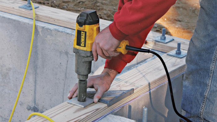
As each mudsill is cut to length, it must be drilled to fit over the foundation bolts. There are many ways to do this, so I’ll explain the method I see most often. Place a length of mudsill stock on the outside of the foundation wall, as close to the bolts as possible and parallel to the chalkline. Measure from the chalkline to the center of a bolt (see the drawing below). Then transfer that measurement to the mudsill, measuring from its inside edge, and make a mark. Now hook your square on the edge of the mudsill, with the corner lined up to the middle of the bolt, and draw a line to the mark. The intersection of the line and the mark is the center point for the bolt hole. When you’ve marked the bolt locations, drill a slightly oversize hole at each mark. The extra room will let you tweak the mudsill to fit perfectly along the layout line on the foundation.

1. Measure from snapped line to center of bolt (A).
2. Measure same distance from edge of sill stock.
3. Align rafter square with center of bolt, and mark where edge of square intersects with measurement for center of bolt hole.
Foundation
Snapped line
Bolt
A
A
Triangular square
Center point of bolt hole
Sill stock
|
|
|


Bolt-Marking JigA fast way to locate holes for foundation bolts is to use a homemade jig. It’s simply a piece of flat metal stock 1 in. or so wide and about 1 ft. long. Cut a half circle in one end of the jig that’s roughly the same diameter as the foundation bolts. The end of the jig should line up with the center of a bolt. Now measure 5½ in. (or the width of your sill stock) from the end of the jig and drill a hole big enough for a pencil. To use the jig, align the mudsill with the inside of the layout line chalked on the foundation. Then at each bolt, simply butt the jig against the bolt and make a mark through the pencil hole.
|

Double-Layer MudsillsIf the foundation is badly out of level or has significant high and low spots, a second mudsill can be added to the first and shimmed level before the joists are installed. You can make room for the nuts and washers by using a large-diameter drill bit and drilling partway through the stock. Holes need be only as deep as the nut and washer. Nail the second sill to the layer below, overlapping joints at the corners, and then shim the second sill to level. The second sill doesn’t have to be pressure-treated wood. Wall sheathing will cover any gaps between the two mudsills.
|

After sliding the sill stock into place over the bolts, put a washer and nut on each one. This house was built in a high-wind zone, so code required large square washers to resist wind uplift. In most areas, though, standard round washers will suffice. If you’re over-zealous drilling the bolt holes, you can replace round washers with larger-diameter fender washers. Hand-tighten the nuts for now.

After all the sills are aligned with the chalklines, tighten each nut further with a wrench. If you opt to use an impact wrench, set the clutch at a fairly light tension so as not to overtighten the nuts. Too much tension can distort the mudsill, making it tough to build a flat and level floor. If using the large square washers, square them to the sill as you tighten the nuts to leave enough room for the rim joist. When the nuts are tight, go back and cut any sill stock that overhangs the foundation. As a final step, check the mudsills with diagonal measurements to make sure they are perfectly square.

Fine Homebuilding Recommended Products
Fine Homebuilding receives a commission for items purchased through links on this site, including Amazon Associates and other affiliate advertising programs.

Bluetooth Earmuffs
Stabila Extendable Plate to Plate Level

11" Nail Puller

View Comments
Thanks for the article. Good tips.
If you trim the outside excess of your mud sill, you will likely end up with an outside edge that is wavy and/or not square, right? If so, while the inside edges of your mud sill are square, what edge of the mud sill do you use as reference for the next layer of framing (ie floor joists and rim board)? If you use the outside edge, won’t that edge be out of square, thus making the floor joists, rim board and subfloor be out of square?