
Installing an Electrical Service
Once you know the steps, mounting and wiring a meter base and breaker panel are easier than you might think.
Synopsis: A step-by-step guide to selecting, sizing, locating, and installing the main components—the meter base, main breaker, and breaker panel—of a new residential electrical system, including a discussion of how to size and install the various types of cable used in the system.
Most people have only a vague sense of how a house’s main electrical panel works, so they wisely keep their hands out of it. But before power is hooked up to a new home, the installation of the meter base and breaker panel is a series of straightforward tasks. Only a few specialized tools are needed, and many of the techniques are the same as those used in branch circuit wiring (See “Rough Electrical Wiring“).
Of course, the trick lies in understanding the National Electrical Code (NEC), knowledge that an electrician gathers over years of apprenticeship and practice. I can’t write an article to replace an electrician’s years of experience, but I can review the essential stages of the process along with the essential aspects of the code. In most jurisdictions, homeowners can install their own electrical service as long as they do the homework, pull the permit, and collaborate with the inspector and the utility company. Changing out an energized, existing service, however, is altogether different and is best left to a qualified, licensed electrician.
The main parts and pieces
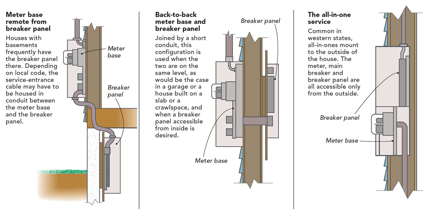
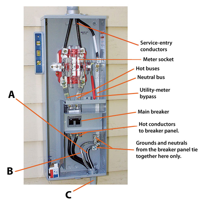
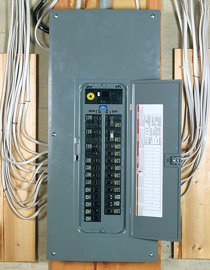
The meter base is where the utility mounts its meter, and the breaker panel is where circuit breakers tie into their individual circuits. The utility has specifications for acceptable meter bases. They can be configured several ways, as shown in the drawings below. Also key is the main breaker, which is integral to either the meter base or the breaker panel. I prefer the main breaker to be in the meter base. Local code frequently requires this location anyway because in the case of a house fire, rescue workers can easily shut down the power. In the project shown here, the meter base and the main breaker are outside, and the breaker panel is in the basement.
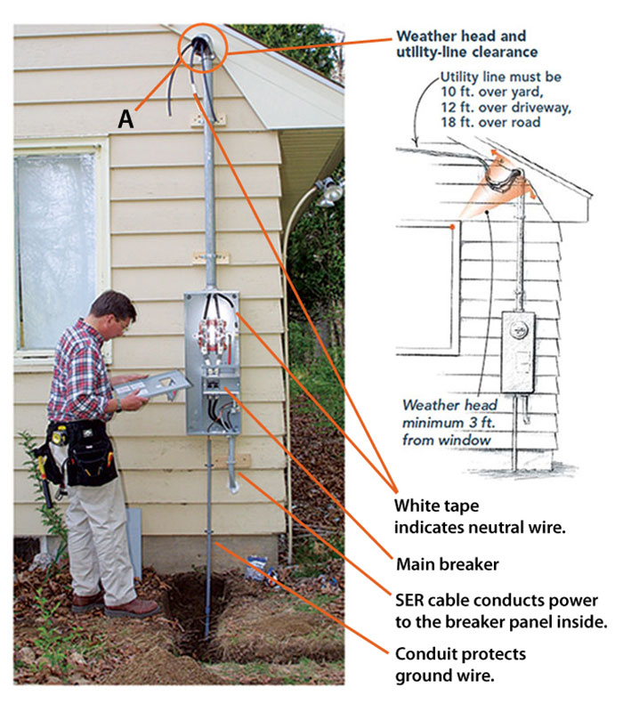
The utility and the building department specify the meter base’s location on the house. My local utility wants it within 36 in. of the corner of the house nearest the transformer, with the center of the meter 60 in. above finished grade. The NEC requires clear workspace 30 in. wide, 36 in. deep, and at least 80 in. high in front of any meter or breaker panel, inside or out. The NEC also specifies clearances from the ground, roof, and windows to the weather head (the top of the mast where an overhead utility cable reaches the house) and the utility cables. Meter bases must be mounted securely, so I lag-screw them to the framing.
Ideally, the breaker panel mounts back to back with the meter base, connected by a short length of metal conduit or a fitting called a chase nipple through which feeder cables will run. This configuration isn’t possible, however, when the breaker panel is in the basement as shown here. In this situation, you have to run a heavy-gauge feeder cable from the meter base to the breaker panel.
Tying the house into the power grid
The utility connects to wires the owner or the electrician runs through 2-in. conduit and out the weather head. If the service is underground, the utility wires into the meter base through owner-supplied conduit.
 |
 |
Wiring the meter base
When power arrives via an overhead service, a conduit called a service riser brings the service cable to the meter base. For the most common size of residential service, 200 amps, I use 2-in. galvanized rigid conduit as a service riser and fasten it to the top of the meter base with a watertight flange called a hub. Conduit clamps hold it to the wall.
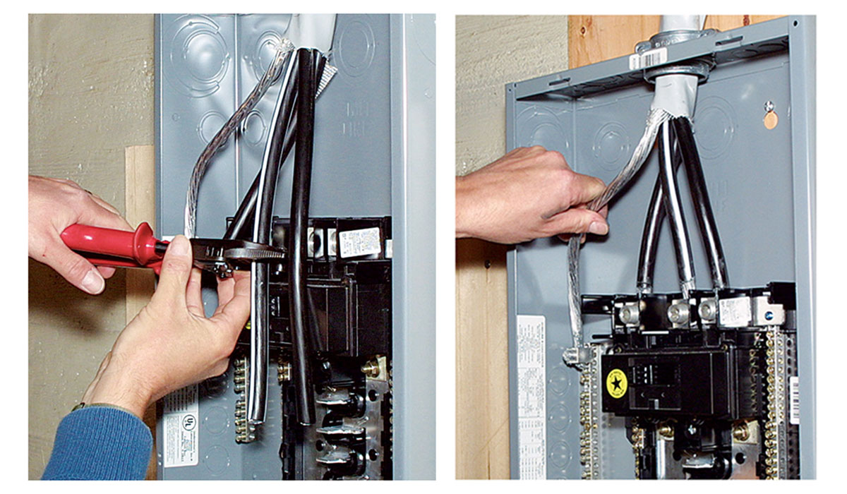
For a 200-amp service, I run three 2/0 (pronounced two ought) copper service-entry conductors through the riser from the meter base (sidebar below). These conductors extend about 2 ft. beyond the weather head for the utility to splice on its supply lines (called a service drop). Two of these conductors, the hots, deliver power to the meter, and one serves as the neutral. Each hot conductor carries 120v relative to the neutral; combining them in the breaker panel yields 240v for large-load appliances such as ranges or air conditioners. I mark the neutral with white electrical tape at both ends before running it through the conduit to keep the conductors straight. (If your service is underground, your responsibility generally is only to run the utilityspecified conduit to the meter base; the utility supplies the wire and hooks it to the meter base when it sets the meter.)
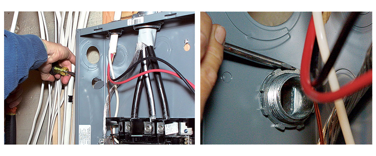
I strip the insulation from the ends of the hots and connect them to the utility side of the meter socket, where the meter will plug in to the base. To ensure that these connections don’t loosen, it’s critical to torque the screws to the specs labeled on the meter base (sidebar above). The neutral affixes to the neutral bus bar (a solid- metal conductor), which goes to the house side of the meter base. On the house side of the meter socket, two bus bars carry power to the main breaker.
Almost ready for the utility to set the meter
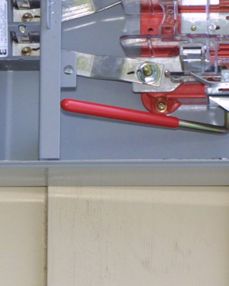
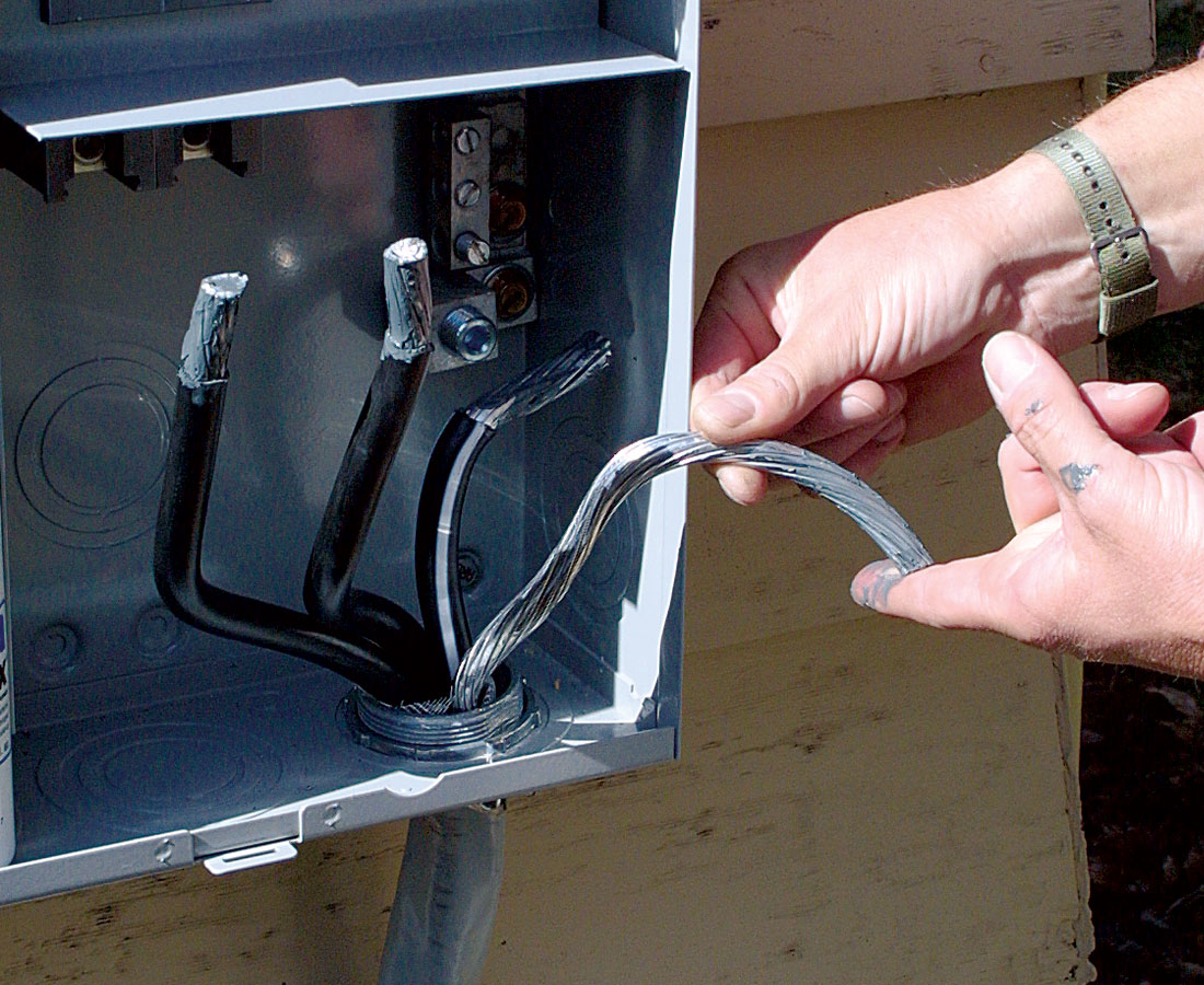
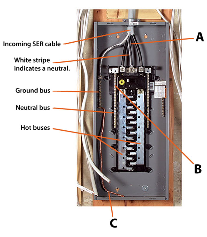
The upper portion of this meter base will be accessible only to the utility once the meter’s set. Because the main breaker is in the meter base, the neutral and ground have to connect to the neutral bus here (bottom photos). A magnetic level frees the author’s hands when he’s affixing the meter base.
 |
 |
 |
From meter base to breaker panel
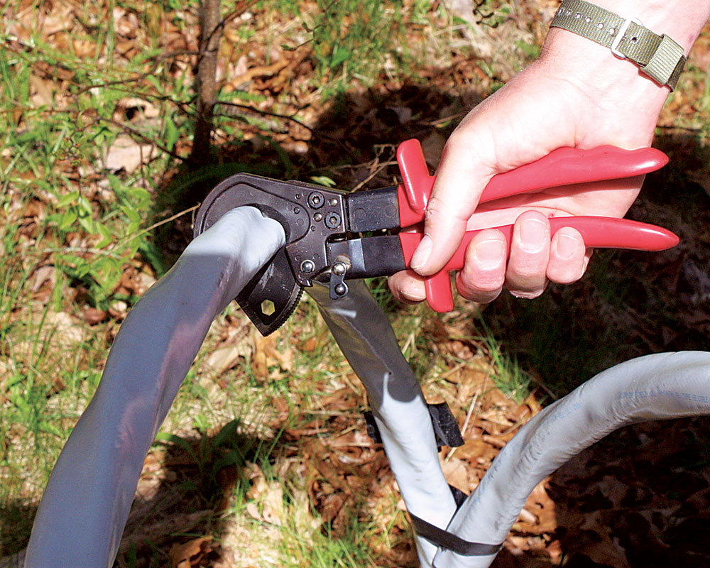
For this 200-amp service, the feeder cable between the meter base and the breaker panel in the basement is type SE, style SER. It has two 4/0 aluminum conductors for the hots and one marked with a white stripe for the neutral, plus a 2/0 aluminum ground conductor. Service-entrance cable (SER) commonly uses aluminum conductors. Copper conducts electricity better than aluminum. Aluminum costs less, though, and if properly installed, it works just fine. Aluminum conductors must be two sizes bigger than copper to carry the same current without overheating.
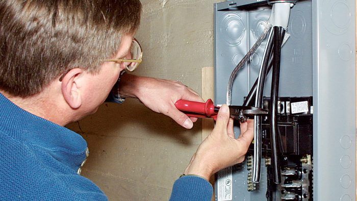
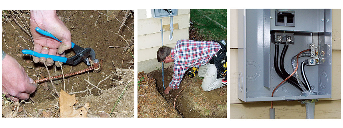
For cable this big, a ratcheting cable cutter comes in handy (photo right, p. 80). This type of cutter is made by Ideal (800-435-0705; www.idealindustries.com), Klein (800-553-4676; www.kleintools.com) and other manufacturers.
The SER is stripped and torqued down to the bus-bar connections on the house side of the meter base, with the neutral and the bare 2/0 ground attaching to the neutral bus. From here, the SER exits the meter base through a cable clamp and enters the house through a hole drilled in the rim joist. Caulk keeps out the elements.
Also attached to the neutral bus is a bare 4-ga. copper wire that runs out through the bottom of the meter base. This grounding-electrode conductor (GEC) attaches with acorn-style clamps rated for direct burial to two 8-ft. long copperplated ground rods driven into the earth. By code, no splices are allowed in the GEC.
How tight is tight enough?
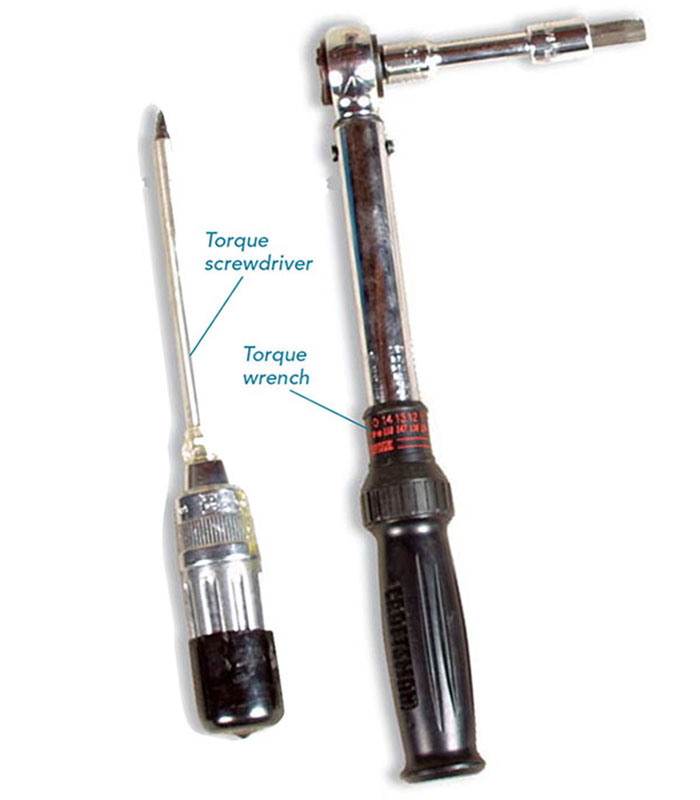 All electrical equipment comes labeled with manufacturer-specified inch-pound values for tightening terminals onto all the conductors. This detail often is overlooked, even by professional electricians, but using a torque wrench (photos right and bottom) or a torque screwdriver (photo left) to tighten all terminals to spec ensures the most secure connection over the years as wires expand and contract with the ebb and flow of electrical current. It’s surprising how tight the conductor terminals need to be, and panels that accept Robertson (square-drive) screwdrivers make the job easier. Torque wrenches are readily available at any auto-parts store, but torque screwdrivers can cost $200 new. I found my Klein 57035 for a bargain price on eBay. —C. A. P. 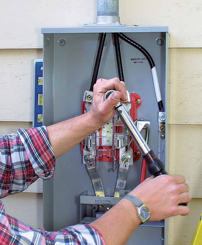 |
What’s up with wire gauges?
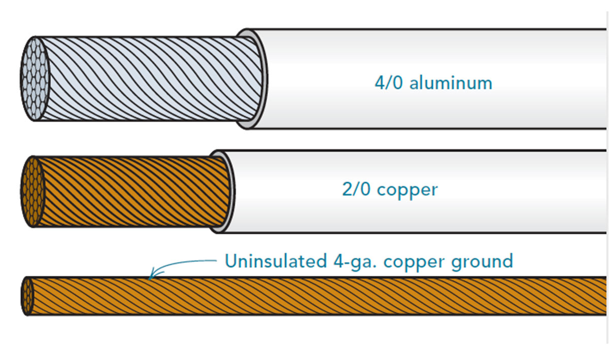 According to American wire gauge (AWG) nomenclature, wires get bigger as the gauge number assigned to them gets smaller. So a 10-ga. conductor is bigger than a 12-ga. conductor. Wire larger than 1 ga. is indicated with zeros: #0, #00, #000 and #0000. These are written as 1/0, 2/0, 3/0 and 4/0, with 4/0 being larger than 2/0. —C. A. P. |
Bigger breaker panels allow safe, reliable service and easy additions
Breaker panels are measured by their maximum current-carrying capacity given in amps and by the number of circuit breakers they can hold. For most homes smaller than 3500 sq. ft. that aren’t heated electrically, a 200-amp panel with 40 or 42 breaker spaces provides enough power with some room for expansion (sidebar above).
I like Square D panels (888-778-2733; www.squared.com). There are plenty of wire spaces in the ground and neutral bars, there’s enough space inside the panel to get my hands in, and I know the breakers still will be available 15 years from now. Cutler Hammer (877-932-9322; www.cutlerhammer.com) also makes good panels. For this house, I chose a panel that has a main breaker in addition to the main breaker at the meter base. While not required, a main breaker here makes life easier by allowing the homeowner to cut power from inside.
Breaker panels should mount as close to where the SER enters the house as possible. Here, I mounted the breaker panel directly below the SER entry. When mounting a breaker panel in a basement, I first affix 3 ⁄ 4-in. plywood or 1x6s to the wall, then attach the panel to the wood to protect it from moisture. The wood also provides a surface for stapling the cables within 12 in. of where they leave the box, as required by the NEC.
Connecting the breaker panel to the meter base
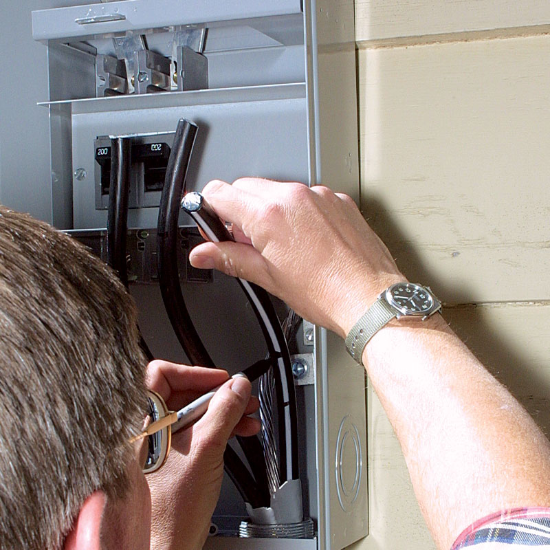
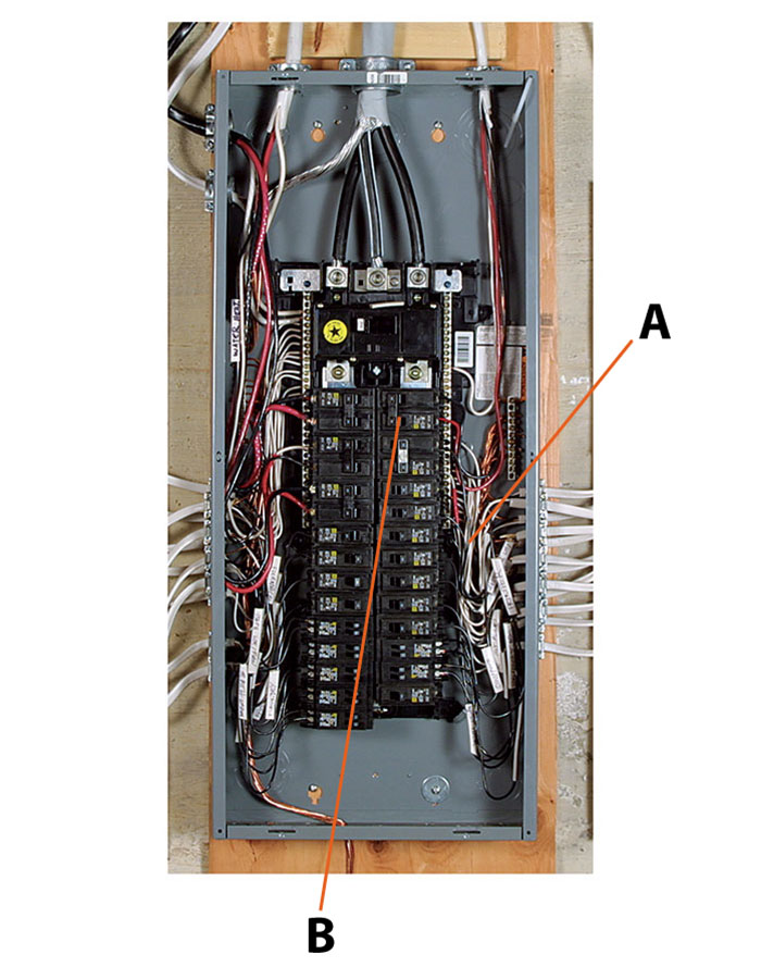
Connecting the hots, neutrals and ground incoming from the meter base to the proper breaker-panel buses is the first step in wiring the panel. Even though there’s a second main breaker in the breaker panel, the ground and neutrals are separate here, connecting only at the first main breaker at the meter base.
 |
 |
Wiring the breaker panel
For panels mounted on the basement wall, I bring the SER through a cable clamp set in one of the large knockouts on top of the breaker panel. After cutting the SER to length, I strip the sheathing and insulation and, again using a torque wrench, attach the conductors to their respective terminals.
In new construction, it’s pretty common to install one breaker now that hooks to a GFCI-protected outlet near the panel. Once that bit of wiring is done, you can call for the panel inspection and then to have the utility set the meter and turn on the electricity to provide power to finish the house.
After all the finish wiring in the house has been done, I can connect the branch circuits to the breaker panel. Be sure to cut all power to the panel by throwing the main breaker at the meter base, not just at the breaker panel, before starting any branch-circuit wiring.
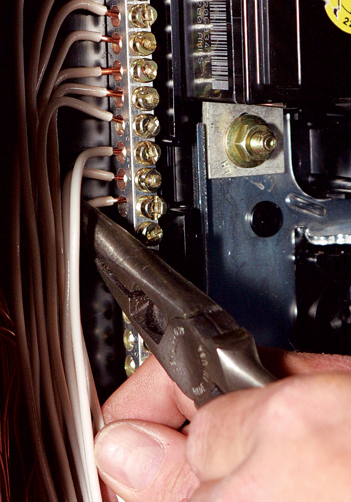
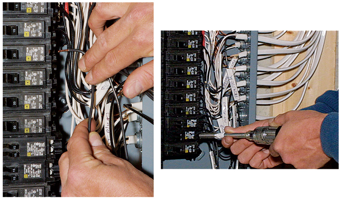
The branch-circuit wiring has to enter the breaker panel through cable clamps installed in the knockouts. Using the knockout that allows the shortest run to the breakers makes dressing all the conductors neatly in the box much easier. Several kinds of clamps are available, including a plastic push-in model. For a panel, I use metal clamps for a solid connection. The locknuts on the clamps should be as tight as possible. The trick here is to get the clamp snug by hand, then tap the locknuts tight with a hammer and screwdriver. Sometimes you have to use pliers to hold the clamp steady from the outside.
When I wire a house, I write the name of each circuit on the end of the cable jacket with a Sharpie. Then, when wiring the panel, I like to tape a circuit schedule to the wall and check all the cables against it. If a circuit has been forgotten or mislabeled, now is the time to discover and fix it.
Service sizingAlthough a 200-amp service is adequate for most residences, calculating the actual load is a good idea, particularly in larger homes or those likely to have high electrical demands, such as electric heat. Also, you may have to show on your permit application how you arrived at a particular service size. Unfortunately, I don’t have the space to tell you how to do this. However, this information is readily available in the NEC, and Code Check Electrical (The Taunton Press, 2002) has a primer on sizing a service. You can also find the information from Code Check Electrical at www.finehomebuilding.com. The NEC allows a maximum of 42 branch circuit breakers in a panel. (Allow two spaces for 240v circuits such as a range or an air conditioner.) If you need more than 42 spaces or more than 200 amps, you can install one meter base rated at 320 amps or 400 amps, then feed two breaker panels from that. After following NEC formulas, I add at least 20% to provide room for expansion. The NEC is designed for safety, not for convenience or comfort. Complying with the code doesn’t guarantee sufficient service. For instance, the start-up current for air-conditioning compressors spikes at five to ten times the motor’s normal running current. Forgetting to account for this sudden inrush of current when ordering service from the utility can cause badly flickering lights when these big motors kick on. —C. A. P.
|
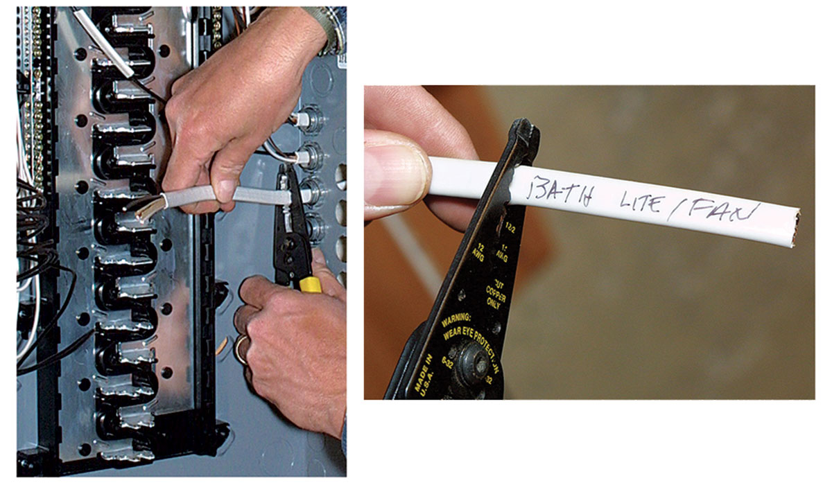
I cut each cable long enough to reach the bottom of the panel and feed the wires into the panel through the clamps. Then I strip the cable to leave at least 1 ⁄ 4 in. of jacket showing inside the panel and save the labeled slug of jacket. I slip the slug over the black 120v (hot) wire and move the hot (240v circuits have two hot wires, one black and either one red or one white indicated as hot with a wrap of black tape) wires off to the side of the panel. Doing so makes room to work with the grounds (bare) and neutrals (white). The clamp should be tightened enough to grip the cable firmly without damaging the insulation.
The NEC requires that grounds and neutrals be kept separate except at the main disconnect (the main breaker). Because this system has its first main breaker outside, the neutral and ground are bonded only at that point, not at the breaker panel. In some breaker panels, the ground and neutral terminal bars may be connected by a bonding jumper. If the main breaker is at the meter base, this jumper must be removed. The information that comes with the panel tells whether you need to do this.
To distinguish between the ground and neutral bars on a panel, look closely at their connections to the body of the panel. Groundterminal bars are screwed directly to the metal body of the panel. Neutral terminal bars are insulated from the panel body.
Starting at the top of the ground bar, I route each ground to a terminal, arranging the conductors neatly as they accumulate and torquing the terminals to spec. Some panel labels say you can attach two or three ground wires under one terminal screw (twisting them together first). With the grounding done, I repeat the process for the neutrals, terminating them at the separate neutral bar. Only one neutral is allowed per terminal.
Bonding metal pipes for safety
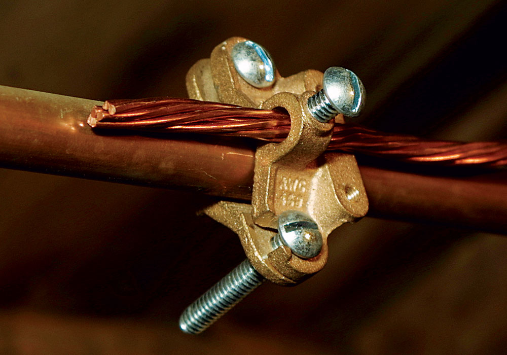
The metal gas and water piping in the house must be connected to the ground bar in the breaker panel. This connection is called bonding; the wire making the connection is called a bonding jumper.
We bond pipes because if a metal pipe is energized inadvertently (because, for example, the insulation fails inside an appliance connected to the pipe), the bonding jumper provides an easy path back to the source so that enough current flows to trip the breaker. If not bonded to the breaker panel’s ground bar, the electrified pipe will sit there waiting to shock or electrocute someone.
I usually bond metal water lines at the water- heater supply pipe, and metal gas pipes as close to the panel as possible. For a 200-amp service, code calls for at least 6-ga. copper to bond metal gas pipes and 4-ga. copper for water pipes; I run 4-ga. copper for both. The larger wire is less prone to physical damage, and I have to carry only one reel of copper to do all the bonding and grounding.
Breakers and hots go in last
Breakers have pressure clips that snap onto the poles of the hot buses. I like to install the high-amperage breakers first, at the top of the hot buses, to keep the current path through the buses as short as possible. Using a torque screwdriver, I connect the wires to the breakers only after snapping all the breakers in place. Neatly looping the wire below its breaker
provides some slack in case a breaker has to be moved or the wire reterminated.
As I install the breakers, I arrange them down both sides of the panel to balance the current between the two hot buses. Balancing the load avoids tripping a main breaker by reducing the load on each hot bus and minimizes the current that flows out on the service-entrance neutral. Achieving this balance requires me to predict which circuits will be used at the same time and how heavily they’ll be used. I arrange 20-amp kitchen-appliance circuits on separate buses because they are likely to be used simultaneously. Fifteen-amp family-room, and kitchen-light and receptacle circuits go on separate buses as well because they’ll be used at the same time every evening. I balance the master-bedroom loads against the other bedrooms and different bathroomreceptacle circuits against each other.
You don’t have to worry about balancing 240v circuits, though. Each 240v breaker has two 120v legs and is self-balancing.
Install the breakers and the cover, then power up
With the service-entry cable tied in and the branch-circuit grounds and neutrals connected to their respective buses, all that’s left to do is install the breakers, place the cover and power up.

Ready to power up
Power up and check the circuits
After the breakers are in and the cover back on the panel, it’s time to power up and check the circuits. There’s always a sense of anticipation when firing up a new panel, but it’s crucial to remember safety procedures. With all breakers turned off, I make sure I’m standing on a dry surface. I use one hand to close the panel’s main breaker, letting power in. The other hand stays in my pocket so that I’m not in contact with the grounded panel housing if something goes wrong.
Powering up one branch circuit breaker at a time, I stand to the side of the panel, not directly in front of it. It’s rare, but there is a slight chance that a newly energized breaker might explode. If a circuit breaker does not hold, the problem could be either a housewiring short or a bad breaker. If you’re lucky, it’s an easy fix. Most likely, though, the circuit breakers will hold, and the last step is to check all the outlets, lights and other devices, and to enjoy watching them all work.
For more information on codesNowhere is adherence to local and national codes more important than in electrical work. Sometimes, though, the two differ. The National Electrical Code (NEC) is revised every three years. Local or state electrical codes are based on a specific edition of the NEC, and they may contain additional, stricter requirements than the NEC. In addition, utility companies have requirements of their own. The best route is to become familiar with the latest version of the NEC, available from the National Fire Protection Association (www.nfpa.org), then find out how the local code differs. Additional resourcesNational Electrical Code 2002 Handbook by Mark Earley et al, National Fire Protection Association. Wiring A House by Rex Cauldwell, The Taunton Press, 2002. Electrical Wiring, Residential, by Ray C. Mullin, Delmar Publishers, 2002. Soares Book on Grounding by J. Phillip Simmons, International Association of Electrical Inspectors, 2002. Pocket Guide to Electrical Installations Under NEC 2002 Volume 1: Residential by Charles R. Miller, National Fire Protection Association, 2001. Code Check Electrical: A Field Guide to Wiring a Safe House by Redwood Kardon, The Taunton Press, 2002. |
Reader Response
Clarifying the electrical code
Having reviewed Clifford A. Popejoy’s article “Installing an Electrical Service” (FHB#150, pp. 78-85), I found errors in his interpretation of the National Electrical Code (NEC):
NEC 230.9(A) – Clearance from Building Openings. The clearance requirements for building openings are from building openings to the service conductors. This clearance requirement would include the conductors in the drip loop. The service shown in the drawing on p. 79 would be found in violation.
NEC 230.24(B)(1) – Vertical Clearance from Ground. The 10-ft. vertical clearance to pedestrian-accessible (only) surfaces is measured from the bottom of the drip l oop. Again this is not what is indicated in the drawing on p. 79.
NEC 230.27 – Means of Attachment. While the porcelain-insulated lag bolt pictured may be acceptable in Sacramento, it will likely not be acceptable to support a service drop in areas with snow and/or ice-load considerations. For these applications a more substantial service support should be used, securely tied into house framing members suitable for the potential weights and tensions imposed by ice-laden service wires.
NEC 230.54(C) – Service Heads Above Service Drop Attachment. While there is an exception for this requirement, “where impracticable,” it could have been met by either extending the service head above the roofline or extending the service entrance conduit up, along the roofline to a point above the point of attachment.
—Dean E. Philips, P. E., via email
Clifford A. Popejoy replies: I agree that the diagram on p. 79 should show more clearly that the clearances include the drip loop. Your third and fourth comments illustrate that there is usually more than one codecompliant way to do a job. The methods and materials you choose depend on local conventions and conditions, and the article illustrates the choices I made for one job.
I wanted to compliment the author of “Installing an Electrical Service” on a well thought out and executed article.
But I’ll offer one point of clarification with regard to the bonding of the metal pipes in the dwelling. Article 250.52 in the 2002 NEC states that “interior metal water piping located more than 5 ft. from the point of entrance to the building shall not be used as a part of the grounding electrode system.” In some areas, it is common practice to bond metal water piping at the water heater. However, this practice is not code-approved. In our jurisdiction, if the water-service piping is copper, a grounding electrode conductor is to be secured to the water pipe within 5 ft. of the point of entry. If no metal water piping is present, two ground rods spaced no less than 6 ft. apart are to be installed as the grounding electrodes.
—Andrew S. Bowman, residential code official, Manheim Township, Lancaster, PA
– Clifford A. Popejoy wires houses for Habitat for Humanity in Sacramento, California.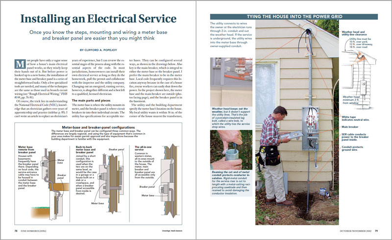
Photos by David Ericson.
Drawings: Mark Hannon.
For more photos, drawings, and details, click the View PDF button below.
From Fine Homebuilding #150

