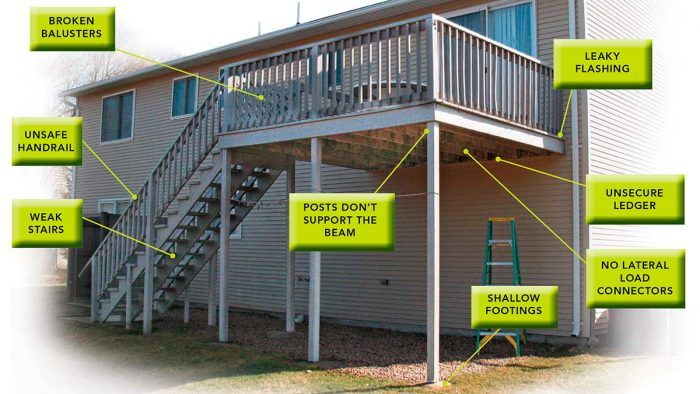
I was at a client’s house only to estimate a front-door replacement, but my eyes were drawn to the second-story deck. From a distance, I could see that the joists on this old deck weren’t supported by a regular beam but were attached to a single rim joist that in turn was nailed only to the side of the 4×4 posts. A closer inspection revealed many other problems: corroding hardware; missing hardware nails; inadequate ledger attachment and flashing; stair stringers pulling away from the frame; and loose, warped guard balusters.
I wasn’t surprised. The houses in the neighborhood were built in the 1970s, and the decks were slapped on without attention to good building practices. There had been local cases of deck collapses. Without preemptive repairs, this deck was a catastrophe waiting to happen.
According to the North American Deck and Railing Association, more than 40 million decks are over 20 years old. You have to wonder how well those decks were constructed before model building codes ramped up minimum standards, not to mention the wear and tear nature inflicts on a deck year after year.
As it turned out, this old deck was worth saving. The framing was solid, and repairs were straightforward because I had easy access to the deck’s underside. I figured it would take only three days of labor and $600 in materials, much cheaper than dismantling and disposing of an old deck and building a new one. I used the American Wood Council’s Prescriptive Residential Wood Deck Construction Guide (also known as the DCA-6), based on the 2009 IRC, as a reference.
Problem #1: Shallow footings
I dug around a couple of footings and found that they didn’t extend below the frost line.
Starting at ground level, the first thing I noticed was that the footings appeared tilted and that the posts were sliding off the tops. I dug around a couple of footings and found that they didn’t extend below the frost line. Combined with their mushroom-shaped tops and unstable surrounding soil, their shallow depth had led to frost heave.
Solution:
Add temporary support. Before excavating the footings, brace the deck with temporary support columns. Set the columns plumb, and tack them in at the top with staging nails or structural screws.
A better footing. After removing the old footings, dig the holes deeper and wider. Based on the footing-size table in DCA-6, footings need to be 16 in. dia. Local code specifies a 40-in. depth. On this job, the author used 12-in.-dia. form tubes with garbage bags taped to the bottom. The bags contain the concrete while permitting it to fill the 16-in.-dia. base entirely at the bottom of the hole. The bags also isolate the concrete from groundwater and soil contamination.
Attach the hardware, then pour. After locating and backfilling the tube, fasten the galvanized post base to the existing post.
Offset for a reason. With the concrete in place, it’s apparent that the post is not centered. The author offset the footing to make room for an additional post to support a new rim beam.
Problem #2: Posts don’t support the beam
The rim beam should be doubled and should rest directly on top of the support posts.
The single rim joist carrying the deck joists was face-nailed to the 4×4 posts, which extend up to become railing posts. Without additional support, nails have the potential to pull out. Ideally, the rim beam should be doubled and should rest directly on top of the support posts.
Solution:
Double the posts. Attach new 4×4 posts to the existing posts with structural screws. The new posts are cut to the height of the rim and rest on galvanized post bases anchored to the new footings
Reinforce the span. The single rim joist spans nearly 6 ft. between posts, far greater than allowed for the deck load. The DCA-6 beam-span table allows a maximum 6-ft. 2-in. span for a double 2×8 southern-yellow pine beam that carries a joist span of 12 ft. After removing the outside decking board, nail a new rim to the existing rim with 16d galvanized nails; then secure each post-rim connection with a galvanized post cap (here, Simpson AC4Z).
Problem #3: Unsecure ledger
The ledger is inadequately attached to the house with washerless 5/16-in. lag screws.
The ledger is inadequately attached to the house with washerless 5/16-in. lag screws and a few randomly driven structural screws. In addition, all the joist hangers are beginning to rust and are missing nails. Where there are nails, they’re the wrong type (6d common nails and 2-in. roofing nails).
Solution:
Will hang. The new joist hangers have two times the galvanized coating of the old hangers. The hangers mounted to the rim beam are nailed with 3-in. HDG common nails. The hangers on the ledger are face-nailed with 1-1/2-in. 10d hanger nails or 1-1/2-in. structural screws.
Space new structural screws according to the manufacturer’s installation table for the deck load and joist span. These 3-5/8-in. screws are long enough to penetrate through the ledger, the wall sheathing, and the house rim joist. They’re staggered 1-3/4 in. from the top and bottom edges of the ledger and are doubled at the ledger ends and joints.
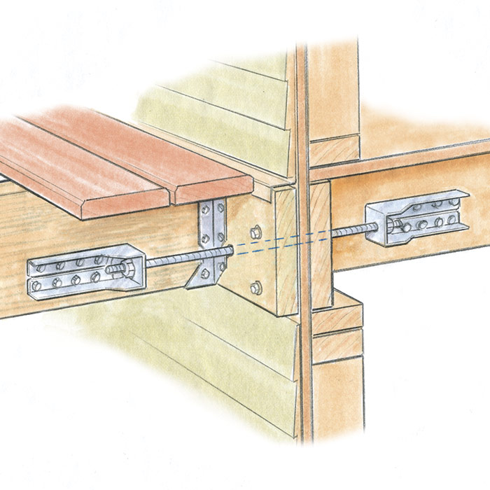
Problem #4: No lateral load connectors
Lateral load connections have been prescriptively addressed in the code only since 2007. While not required on existing decks, they’re a well-advised upgrade to elevated decks. The lateral connection joins a deck joist to a joist inside the house. Two connections per deck are all that’s needed. After running the bolt or rod from the inside out through the ledger, position the deck-joist hardware and screw it in place. Add a bead of sealant to waterproof any gap between the rod and ledger.
Solution:
The lateral connection joins a deck joist to a joist inside the house.
Two connections per deck are all that’s needed.
Problem #5: Leaky flashing
The thin aluminum ledger flashing is inadequate.
The thin aluminum ledger flashing is inadequate and is corroded in several spots. Left as is, the flashing will allow water behind the ledger, which in turn will cause rot and a potential deck failure. A more robust flashing system should include self-adhering membrane and flashing with a taller wall leg.
Solution:
Prepare for framing. Remove the door riser board, the siding, and the first deck board to inspect for rot. After folding up the housewrap, cut a shallow kerf in the joist tops for the flashing edge.
Layers of protection. After applying a strip of self-adhering membrane to the top of the ledger and onto the wall, install new flashing (everflashing.org) over the ledger.
Counterflash the metal flashing with another piece of self-adhering membrane, and fold the housewrap back down over the wall leg.
Problem #6: Broken balusters
Several balusters are broken and loose.
The spaces between most of the guard balusters are greater than the code limit of less than 4 in. Several balusters are warped or broken, and most are loose, attached only by a single nail at each end.
Solution:
A better way to space balusters. Here’s a trick from FHB’s “Tips & Techniques” (#77, p. 30). Stretch a length of 3⁄4-in.-wide waistband elastic, and mark lines at 5 1⁄4-in. increments (4-in. space plus the width of a baluster). Pin a line at one end of the deck rail, and stretch the elastic to the opposite end. Adjust the stretch until the spacing between lines is less than 5 1⁄4 in. (the code baluster-space limit of less than 4 in. plus the baluster width). Pin a line 1 1⁄4 in. past the end of the rail. Transfer the lines onto the railing, and align the baluster edges with the lines.
Secure the railing. Remove the balusters from each rail section, and replace the bad ones. For a better connection, drill pilot holes into each end of the balusters, and fasten them to the 2×4 rails with four screws, two at each end.
Problem #7: Unsafe handrail
According to code, stairs need at least one handrail continuous from top to bottom and whose ends either terminate onto newels or return safely. Here, the handrail ends run long and don’t have safety returns onto the guardrail.
Solution:
Return for safety. The author trimmed the extralong handrail and guardrail, then mitered the handrail to make a safety return. He glued and screwed the top and bottom returns to the rail to wrap around the end of the guardrail.
Problem #8: Weak stairs
After a quick inspection, I found a handful of problems with the stairs. The tops of the stringers had pulled away from the header. The stringer cuts extended past the notches into the structural area. (The DCA-6 requires an uncut structural area of at least 5 in.) The stringer’s span was too long and spaced too wide without intermediate support. Finally, the stringer header itself had no supporting jacks and was nailed only to the posts.
Stringers pulling away
Weakened stringers
Too long, too wide.
Solution:
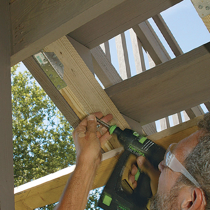
Double up. Issues of span, spacing, and overcut stringer notches can be resolved by sistering 2x6s along each stringer. To make it easier to fit them into place, cut the 2x6s short so that they can rest on ground-contact pressure-treated 4×4 blocks. Nail the 2x6s to the stringers with two rows of 12d galvanized nails, 12 in. on center.
Hardware reinforces the connection. Screw galvanized stringer connectors (Simpson LSCZ or similar) to the header and to the new 2x6s to prevent the stringers from pulling away.
The header needs support. Position 2×4 pressure-treated jacks from the footings to beneath each end of the stringer header, and attach them to the 4×4 posts with structural screws.
—Mike Guertin is a builder in East Greenwich, R.I., and editorial adviser to Fine Homebuilding. His website is mikeguertin.com. Photos by Charles Bickford, except where noted.
Fine Homebuilding receives a commission for items purchased through links on this site, including Amazon Associates and other affiliate advertising programs.
4-Gallon Piston Backpack Sprayer
This sprayer holds a large amount of solution and the backpack design keeps your hands free, making maintaining and cleaning a deck a breeze.
This tool is nice to have for fitting in tight spaces when fastening hardware. While you may not use it often, you'll be glad you have it when you need it.
How many footings total were replaced at the stairs? Curious with the sistered stringers if you abandoned the midspan stringer footings.
How was digging around the 4x4s more cost effective vs installing the beam under the joists where the old footings wouldn't get in the way, when you account for the time to set up temporary supports, pulling the old footings, and digging with a post in your face?
Now I ask to visualize a slightly different scenario. If the band joist where the stairs attach was attached to the house, as in if the house had a bump out for half the joist span, would you have ditched that footing entirely? Replacing only three footings along the rim.
This is a dialog window which overlays the main content of the page. The modal window is a 'site map' of the most critical areas of the site. Pressing the Escape (ESC) button will close the modal and bring you back to where you were on the page.


View Comments
How many footings total were replaced at the stairs? Curious with the sistered stringers if you abandoned the midspan stringer footings.
How was digging around the 4x4s more cost effective vs installing the beam under the joists where the old footings wouldn't get in the way, when you account for the time to set up temporary supports, pulling the old footings, and digging with a post in your face?
Now I ask to visualize a slightly different scenario. If the band joist where the stairs attach was attached to the house, as in if the house had a bump out for half the joist span, would you have ditched that footing entirely? Replacing only three footings along the rim.
Thanks Mike!